ON1BES Labo 2020 |
Digital RF Wattmeter OZ2CPU |
 Back to Home-page |
Calibrated RF Power Meter
This is my built version of the RF Power Wattmeter from oz2cpu.
Published in Elektor Magazine 2002, In the September issue of CQ-PA, and on the oz2cpu site itself (for link, see below).
For a radio amateur, a watt meter can be very useful. This meter can be used to measure the gain in RF amplifiers, measuring the bandwidth of filters, measuring field strength of antennas, measuring radiated power, SWR and other matters.
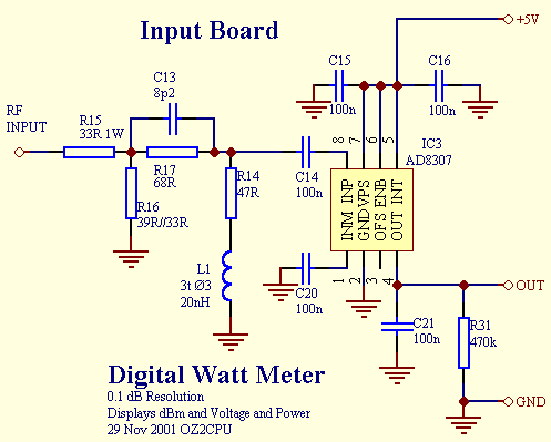
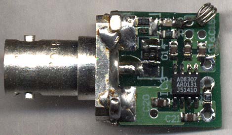
This RF watt meter uses an AD8307 to measure the RF signal. The AD8307 circuit is frequency compensated, and optimized for losses to achieve an optimal SWR over a wide frequency range.
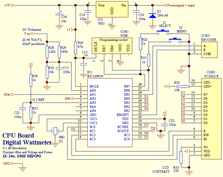
There is a PIC16F876 with internal 10-bit analog to digital converter to the analog output of the AD8307 to a digital value, and to put it on the LCD display. A comparison table converts the measured dBm values into RF voltages and RF power (watts) values.
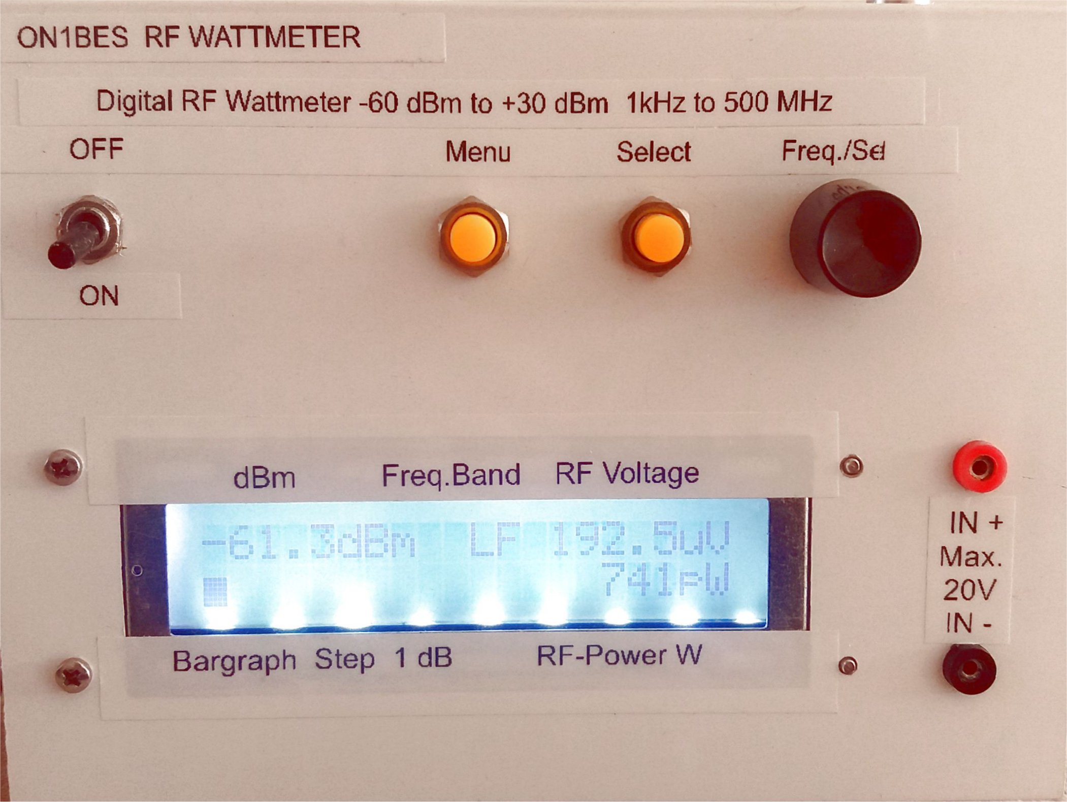
The 2x20-character display indicates the following data:
o the measured value in dBm
o the status of the frequency band used
o the RF value in µV or mV
o a signal barograph line in 1 dBm blocks
o the power in pW or mW
o frequency break without calibration is 1 kHz to +/- 950 Mhz (relative mode)
o frequency range after the calibration is 1 kHz to +/- 500 MHz
o accuracy without calibration is +/- 1 dB from 1MHz to 450MHz
o accuracy after calibration is 0.2 dBm on each frequency band
o input SWR varies from 1.00 to 1.30, depending on the measuring frequency
o input power range is -60 to +30 dBm (1 nW to 1 Watt)
o it is possible to measure relative power up to +/- 950 MHz
o an additional input is provided as a digital volt meter (max. 1 to 20 Volt DC)
o the software can adjust the 0 dBm point to 5 different frequencies, so that the meter precision is around 0.5 dBm
o note: to measure larger signals above 1 watt, a calibrated attenuator is required, e.g. 40 dBm
The module with the AD8307 must be constructed according to the HF / UHF rules, and can also be best protected.
Battery operation is quite possible if the LCD lighting is switched off, or does not use more than 100 mA.
For this I have replaced the original LEDs in the LCD with white LEDs that consume much less.
Circuit:
Photo's :
 |
 |
|
Front panel
|
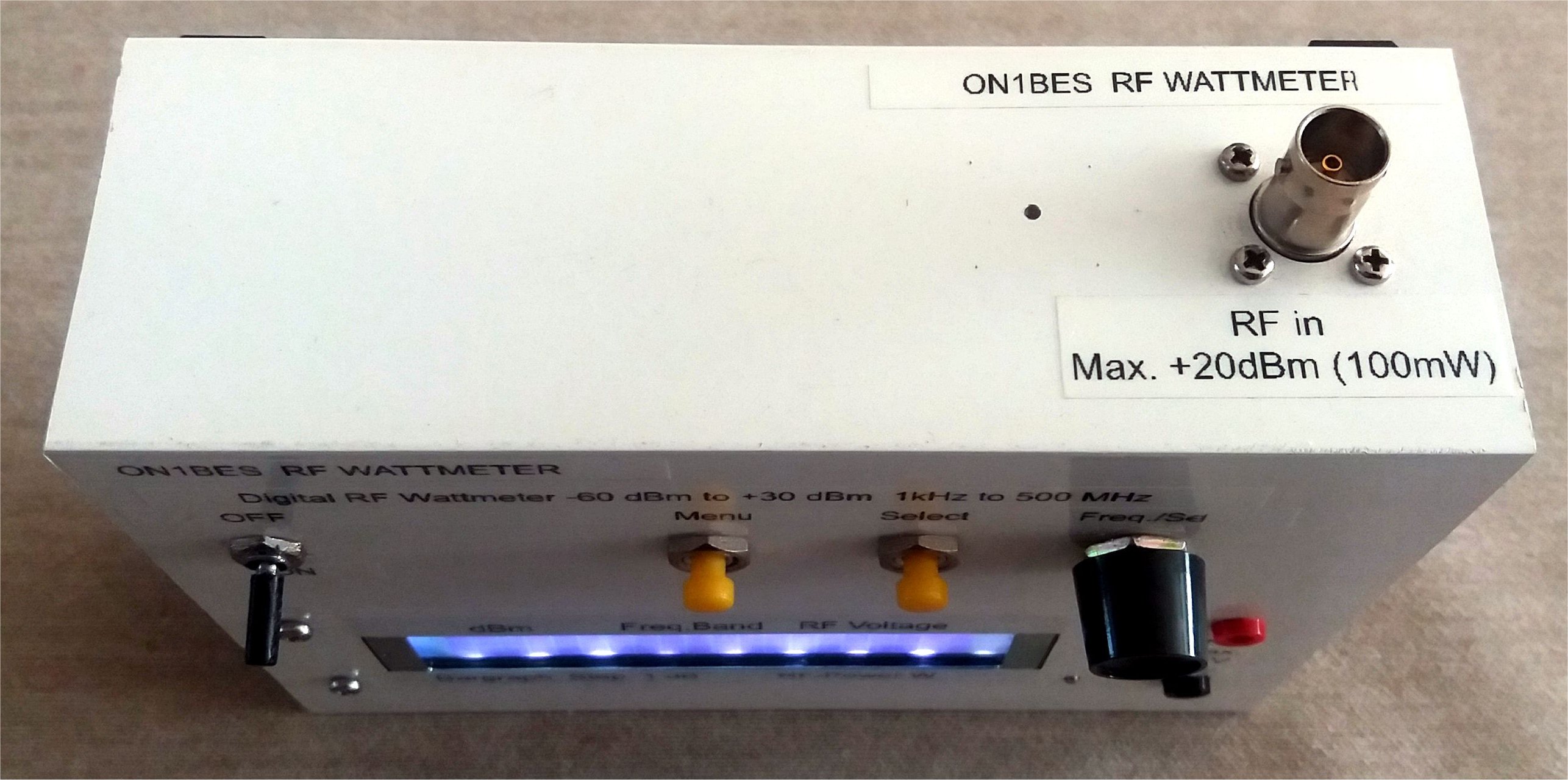
Top with Input Module
|
Input Module :
|
|
|
Circuit Input Module
|
Build Input Module
|
Downloads : none
Links :
Mainpage : http://www.webx.dk/oz2cpu/radios/miliwatt.htm
Software and download : http://www.webx.dk/oz2cpu/radios/milli-soft104.htm
OZ2CPU digitale RF mW-dBm-mV meter : http://www.bolkesteijn.nl/blog/index.php?page=oz2cpu-meter
Elektor : elektor_02a016.pdf
Google - search for: Digital Wattmeter oz2cpu
 Mail: on1bes(at)Scarlet.be