
ON1BES Labo 2018 |
Labo talk 2018 |

Back to Homepage |
Voor NL versie klik hier
SDR Antenna choices, the simple explanation
I get a lot of questions about SDR antennas. However, many are only interested in scanner receiving or weather-photos.
But it does not work like that. For whom SDR radio is new, or has no radio technology background, it is best to read this article.
To answer this question, we first have to briefly explain how radio waves can be received.
In the first place, EVERY antenna is derived in practice from a DIPOLE.
A DI-POLE, that are 2 equal wires or bars in one line, one receives the negative part, and the other the positive part of the radio wave.
Radio waves, however, have an alternating voltage, which changes on frequency.
For example, a radio wave at 10MHz (10 Megahertz) alternates 10,000,000 times per second, or 10,000,000 periods per second of polarity , so also the signal that is received on the dipole.
Radio signals travel at about the speed of light or 300,000,000 meters / sec.
At a reception frequency of 10MHz we can then calculate the wavelength of our antenna with the formula:
Wavelength in meters = 300 / Freq (in MHz) = ~ 30 m. So we would need a wire of 30 meters !
For practical reasons, a dipole is made at half of one period (1 period = 1 wavelength = here 15m for 10MHz), because of the changing field.
We must be able to feed the dipole in the middle, because there is too high a voltage on the ends, and we can not connect our antenna cable to it.
So we divide the dipole of 15m into 2 pieces of 7.5m. Now it is possible to receive current and voltage on our dipole at a frequency of 10Mhz , because the current in the middle goes through the zero point and thus is also low at our feeding point.
In order to receive another frequency ideally, we would therefore always have to adjust the length of the dipole, which is not possible in practice.
In order to solve this, the dipole is made slightly more broad-band with some artificial handles.
But the transmitter / receiver usually requires an antenna tuner to be able to tune exactly to a certain frequency.
If you do not, then there is a chance that you will damage the transmitter during broadcasting.
If you just want to receive, this problem is not there, but the reception sensitivity without a tuner can decrease.
In the middle of a dipole, the bars / wires are connected to a power cable that goes to the receiver / transmitter.
This line of supply is always symmetrical to a dipole, so with 2 parallel wires to the receiver.
This type of power cable was formerly the most used in transmitters / receivers.
Remember that in the past the TV sets also had that flat cable (color in black or white).
This antenna system with symmetrical power cable has in practice a transport resistance (impedance) of approximately 300 ohms.
The transmitter / receiver input is adapted to this, for low-loss transport of the radio waves.
If (as nowadays) a coax cable is used (= asymmetric cable), a transducer (balun) must be placed near the antenna to use an asymmetrical power supply cable.
Otherwise, a part of the radio signal is short-circuited to the ground (shielding), and we do not want that.
This converter can e.g. with an extra piece of coax cable, or with a (toroidal) transformer.
In this way, the 300 ohm resistance can be converted to usually 75 or 50 ohms.
Most receivers are adapted to this resistance, so that low-loss signal transmission is possible.
A standard SDR stick also has an input resistance of 75 ohms (just like the smaller TV sets).
Many fixed radios still have a 300 ohm antenna input, to connect a flat cable antenna.
A standard dipole will be of little use as an SDR antenna , because in principle it is sensitive to only one frequency.
The length of the dipole determines which radio wave (wavelength), or frequency is best received on the antenna.
All other radio waves are then weakened . Moreover , a horizontally suspended dipole is only sensitive in 2 opposite directions.
A vertical dipole receives more around radio signals. This also applies to the included SDR stock antenna.
Although positioned vertically, and therefore all around sensitive, this is still a simple dipole, and therefore can only be used on a very limited number of frequencies.
There is also no resistance (impedance) adjustment to the 75 ohm cable, so that a part of the received signal is already short-circuited.
Moreover, this small antenna needs a good base (mass), by e.g. to place on a large metal surface. Compare it with a car antenna roof.
If you look into the base of the antenna, you notice that usually the ground wire (shielding) is not even connected , which is an additional problem.
In this way, the interference signals present have free play to reach the antenna.
This does not matter much for strong TV DVB-T or Radio stations , but for SDR the more.
Some included slide-out SDR antenna sets can be adjusted to the desired frequency by sliding in or out.
For the SDR with its very wide frequency range, we therefore need a better antenna that can receive multiple frequencies.
Examples of a broadband antenna are e.g. a discone antenna, a vertical duo or 3-band antenna, a collinear antenna or a coax antenna.
Here is work to the store to look up Google.
In any case, it is already very worthwhile to make a random coax antenna of e.g. an old video cable with a BNC plug.
The costs are practically zero, and you do not need any special tools.
On my website you will find enough information about that. A number of modifications on standard SDR antennas , have also been described.
This story is about the standard SDR reception on VHF-UHF (~ 24MHz - 1.2GHz), but that also applies to the extension of reception to the HF bands (0-30 MHz).
To receive the HF bands, you need an SDR HF Upconverter. The sometimes described 'direct sampling' method gives rather poor results.
If you are looking for radio stations with an SDR receiver for the first time, you will probably get a nasty surprise, because apart from a few FM stations, many 'false' signals, AND a strong noise, can not be received much.
Therefore, here is some explanation how that comes. For strong broadcasting stations, or on the short wave, a piece of wire that hangs somewhere in the room at the window is enough.
But this room antenna, and certainly the included SDR rod antenna, also picks up all sorts of disturbances from the environment of electrical cables and appliances.
An important detail is that at higher frequencies the signal no longer stays neatly in the cable, but moves to the edge of the conductor (Google: Skin effect).
But the shielding of the cable will also lose some of its properties, and any longer shielding on a cable will start to work itself as an antenna, and that is not the intention!
The current digitization has led to a huge increase in local background noise that makes indoor reception virtually impossible.
Reception can be improved by choosing the right antenna type and placing it at a certain height outdoors.
Unfortunately, we still have faults on our receiver input, which usually come from a contaminated ground line or edge ground.
(NEVER use the protective earth of an power outlet as an antenna ground).
Even if the antenna delivers an absolutely clean signal, it is ruined by the dirty ground connection (mantle currents).
Both voltages, good signal and fault signal are added to the antenna input, so that weak signals disappear in strong background noise.
Solutions for avoiding a contaminated earth conductor are e.g. placing ring cores (from ferrite or iron powder) in all power wires and also USB cables.
You can already find them on the better USB cables, and power adaptor cables for Laptops and LCD screens. No cheap solution.
Mantle current coils can be placed in the antenna line (Google: common mode chokes), which also have a favorable effect on the reception.
The coils are usually placed at the point where the antenna cable leaves the house, and at the feed point of the antenna itself.
Both the antenna (foot) and the receiver require a separate grounding. At the receiver side, the antenna cable is usually earthed to the ground, at the point where the cable leaves the house.
In this way, failures can not creep up the cable and reach the antenna.
This is perfectly described in articles about active antennas such as the MiniWhip, about possible disruption of these and other antennas.
You can also make a mantle current coil yourself by making a number of windings (6 to 10) on a 5cm coil PVC tube with the antenna cable itself.
With such an active antenna, an isolating transformer is sometimes also placed in the antenna line in order to interrupt the polluted earth.
Unless one can make it yourself, the price tag will increase considerably in order to have a reasonable receipt with an SDR Stick.
There are very beautiful articles written that deal with this matter.
Link's :
SDR Antenna choices, the simple explanation
_______________________________________
I get a lot of questions about SDR antennas. However, many are only interested in scanner receiving or weather-photos.
But it does not work like that. For whom SDR radio is new, or has no radio technology background, it is best to read this article.
Which antenna do I need for SDR?
To answer this question, we first have to briefly explain how radio waves can be received.
In the first place, EVERY antenna is derived in practice from a DIPOLE.
A DI-POLE, that are 2 equal wires or bars in one line, one receives the negative part, and the other the positive part of the radio wave.
Radio waves, however, have an alternating voltage, which changes on frequency.
For example, a radio wave at 10MHz (10 Megahertz) alternates 10,000,000 times per second, or 10,000,000 periods per second of polarity , so also the signal that is received on the dipole.
 |
 |
 |
 |
| Wire Dipole | Rod Dipole | Vertical Dipole | FM TX and a Groundplane |
Calculate the length of our antenna or dipole.
Radio signals travel at about the speed of light or 300,000,000 meters / sec.
At a reception frequency of 10MHz we can then calculate the wavelength of our antenna with the formula:
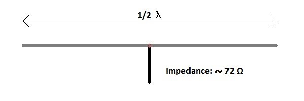
Wavelength in meters = 300 / Freq (in MHz) = ~ 30 m. So we would need a wire of 30 meters !
For practical reasons, a dipole is made at half of one period (1 period = 1 wavelength = here 15m for 10MHz), because of the changing field.
We must be able to feed the dipole in the middle, because there is too high a voltage on the ends, and we can not connect our antenna cable to it.
So we divide the dipole of 15m into 2 pieces of 7.5m. Now it is possible to receive current and voltage on our dipole at a frequency of 10Mhz , because the current in the middle goes through the zero point and thus is also low at our feeding point.
In order to receive another frequency ideally, we would therefore always have to adjust the length of the dipole, which is not possible in practice.
In order to solve this, the dipole is made slightly more broad-band with some artificial handles.
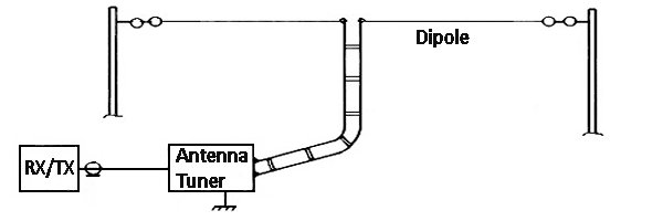
But the transmitter / receiver usually requires an antenna tuner to be able to tune exactly to a certain frequency.
If you do not, then there is a chance that you will damage the transmitter during broadcasting.
If you just want to receive, this problem is not there, but the reception sensitivity without a tuner can decrease.
 |
 |
 |
 |
| 1/2 Wave Dipole | Voltage and Current | Broadband Dipole | Antenna and Tuner |
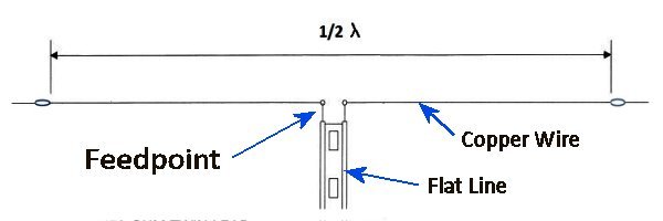
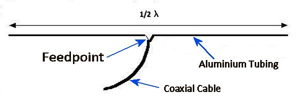
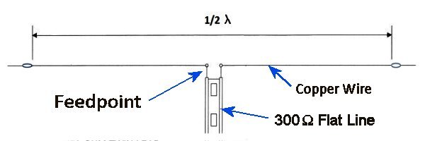
The antenna power feed point.
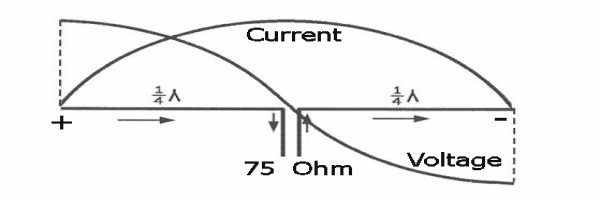
In the middle of a dipole, the bars / wires are connected to a power cable that goes to the receiver / transmitter.
This line of supply is always symmetrical to a dipole, so with 2 parallel wires to the receiver.
This type of power cable was formerly the most used in transmitters / receivers.
Remember that in the past the TV sets also had that flat cable (color in black or white).
This antenna system with symmetrical power cable has in practice a transport resistance (impedance) of approximately 300 ohms.
The transmitter / receiver input is adapted to this, for low-loss transport of the radio waves.
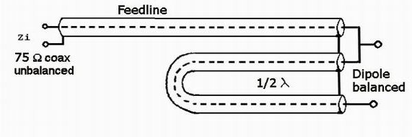
If (as nowadays) a coax cable is used (= asymmetric cable), a transducer (balun) must be placed near the antenna to use an asymmetrical power supply cable.
Otherwise, a part of the radio signal is short-circuited to the ground (shielding), and we do not want that.
This converter can e.g. with an extra piece of coax cable, or with a (toroidal) transformer.
In this way, the 300 ohm resistance can be converted to usually 75 or 50 ohms.
Most receivers are adapted to this resistance, so that low-loss signal transmission is possible.
A standard SDR stick also has an input resistance of 75 ohms (just like the smaller TV sets).
Many fixed radios still have a 300 ohm antenna input, to connect a flat cable antenna.
 |
 |
 |
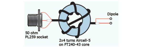 |
| Symetric Power Supply | A-Symetric Power Supply | Coax Matching | Ringcore Matching |
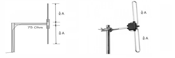
The efficiency of the SDR antenna.
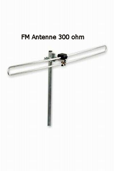
A standard dipole will be of little use as an SDR antenna , because in principle it is sensitive to only one frequency.
The length of the dipole determines which radio wave (wavelength), or frequency is best received on the antenna.
All other radio waves are then weakened . Moreover , a horizontally suspended dipole is only sensitive in 2 opposite directions.
A vertical dipole receives more around radio signals. This also applies to the included SDR stock antenna.
Although positioned vertically, and therefore all around sensitive, this is still a simple dipole, and therefore can only be used on a very limited number of frequencies.
There is also no resistance (impedance) adjustment to the 75 ohm cable, so that a part of the received signal is already short-circuited.
Moreover, this small antenna needs a good base (mass), by e.g. to place on a large metal surface. Compare it with a car antenna roof.
If you look into the base of the antenna, you notice that usually the ground wire (shielding) is not even connected , which is an additional problem.
In this way, the interference signals present have free play to reach the antenna.
This does not matter much for strong TV DVB-T or Radio stations , but for SDR the more.
Some included slide-out SDR antenna sets can be adjusted to the desired frequency by sliding in or out.
 |
 |
 |
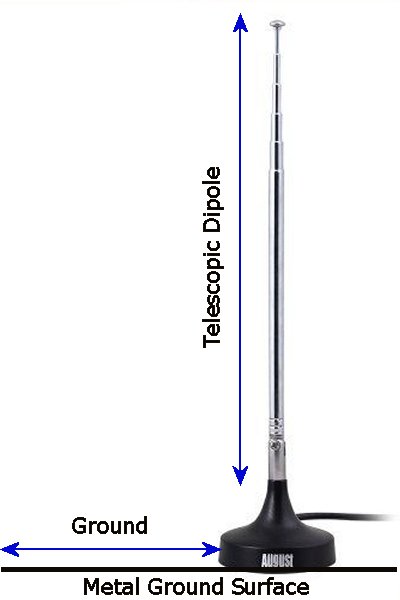 |
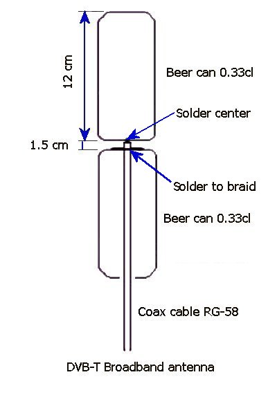
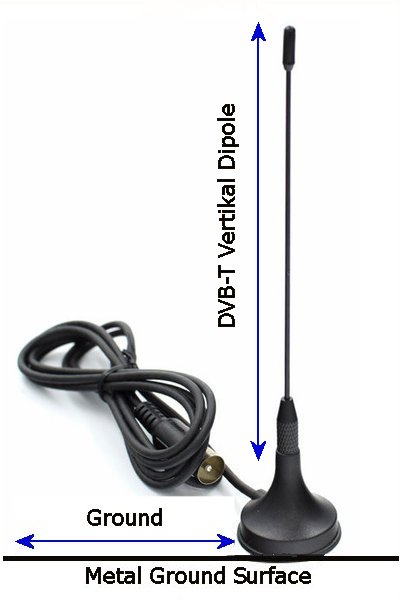
| Horizontal Dipole FM Antenna | Vertical Beer-Can Dipole | Vertical Dipole DVB-T | Telescopic Vertical Antenna |
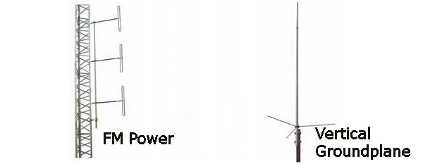
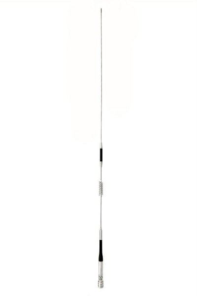
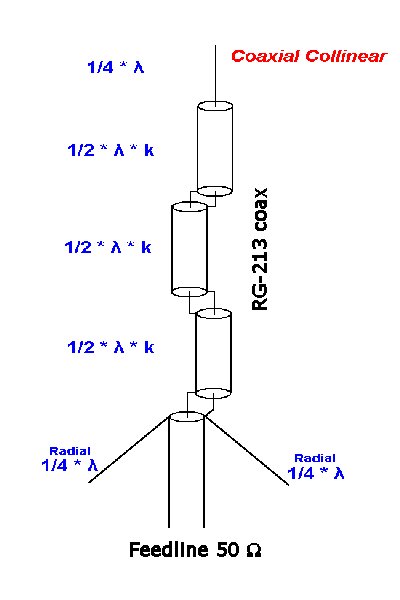
A better SDR antenna.
For the SDR with its very wide frequency range, we therefore need a better antenna that can receive multiple frequencies.
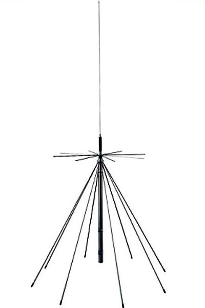
Examples of a broadband antenna are e.g. a discone antenna, a vertical duo or 3-band antenna, a collinear antenna or a coax antenna.
Here is work to the store to look up Google.
In any case, it is already very worthwhile to make a random coax antenna of e.g. an old video cable with a BNC plug.
The costs are practically zero, and you do not need any special tools.
On my website you will find enough information about that. A number of modifications on standard SDR antennas , have also been described.
 |
 |
 |
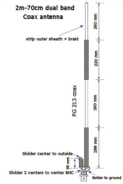 |
| Broadband Discone Antenna | 3-Band Car Antenne | Collineair Coax Antenna | 2 Band Coax Antenna |
Disturbance of an SDR antenna.
This story is about the standard SDR reception on VHF-UHF (~ 24MHz - 1.2GHz), but that also applies to the extension of reception to the HF bands (0-30 MHz).
To receive the HF bands, you need an SDR HF Upconverter. The sometimes described 'direct sampling' method gives rather poor results.
If you are looking for radio stations with an SDR receiver for the first time, you will probably get a nasty surprise, because apart from a few FM stations, many 'false' signals, AND a strong noise, can not be received much.
Therefore, here is some explanation how that comes. For strong broadcasting stations, or on the short wave, a piece of wire that hangs somewhere in the room at the window is enough.
But this room antenna, and certainly the included SDR rod antenna, also picks up all sorts of disturbances from the environment of electrical cables and appliances.
An important detail is that at higher frequencies the signal no longer stays neatly in the cable, but moves to the edge of the conductor (Google: Skin effect).
But the shielding of the cable will also lose some of its properties, and any longer shielding on a cable will start to work itself as an antenna, and that is not the intention!
The current digitization has led to a huge increase in local background noise that makes indoor reception virtually impossible.
Reception can be improved by choosing the right antenna type and placing it at a certain height outdoors.
Unfortunately, we still have faults on our receiver input, which usually come from a contaminated ground line or edge ground.
(NEVER use the protective earth of an power outlet as an antenna ground).
Even if the antenna delivers an absolutely clean signal, it is ruined by the dirty ground connection (mantle currents).
Both voltages, good signal and fault signal are added to the antenna input, so that weak signals disappear in strong background noise.
Solutions for avoiding a contaminated earth conductor are e.g. placing ring cores (from ferrite or iron powder) in all power wires and also USB cables.
You can already find them on the better USB cables, and power adaptor cables for Laptops and LCD screens. No cheap solution.
Mantle current coils can be placed in the antenna line (Google: common mode chokes), which also have a favorable effect on the reception.
The coils are usually placed at the point where the antenna cable leaves the house, and at the feed point of the antenna itself.
Both the antenna (foot) and the receiver require a separate grounding. At the receiver side, the antenna cable is usually earthed to the ground, at the point where the cable leaves the house.
In this way, failures can not creep up the cable and reach the antenna.
This is perfectly described in articles about active antennas such as the MiniWhip, about possible disruption of these and other antennas.
You can also make a mantle current coil yourself by making a number of windings (6 to 10) on a 5cm coil PVC tube with the antenna cable itself.
With such an active antenna, an isolating transformer is sometimes also placed in the antenna line in order to interrupt the polluted earth.
Unless one can make it yourself, the price tag will increase considerably in order to have a reasonable receipt with an SDR Stick.
There are very beautiful articles written that deal with this matter.
Link's :
Collinear, Grondplane and MiniWhip :
Collinear antenna
Ground Plane antenna and others
Development of VHF Collinear Antennas
Fundamentals of the MiniWhip
SDR noise suppression :
Reducing RTL Dongle internal spurii and noise signals
Grounding of MiniWhip and other active whip antennas
Discone antenna for RTLSDR
_____________________________________________________________________________________________________________________
Downloads :
None
 mail: on1bes at Scarlet.be
Collinear antenna
Ground Plane antenna and others
Development of VHF Collinear Antennas
Fundamentals of the MiniWhip
Reducing RTL Dongle internal spurii and noise signals
Grounding of MiniWhip and other active whip antennas
Discone antenna for RTLSDR