ON1BES Labo 2022 |
SDR HF-Upconvertor USB v5.0 |
 Back to Home-page |
Voor NL versie klik hier
SDR HF-Upconverter v5.0 with USB - also for the V3 RTL-SDR
Is this the smallest SDR HF Up converter you know? Let me know !
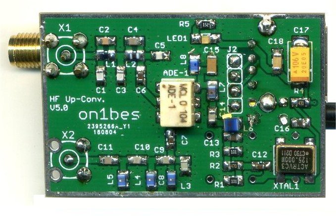 This version 5.0 is a proprietary design. The PCB is made by a PCB manufacturer.
It is a design for the self-builder, who still has some SMD parts in the drawer.
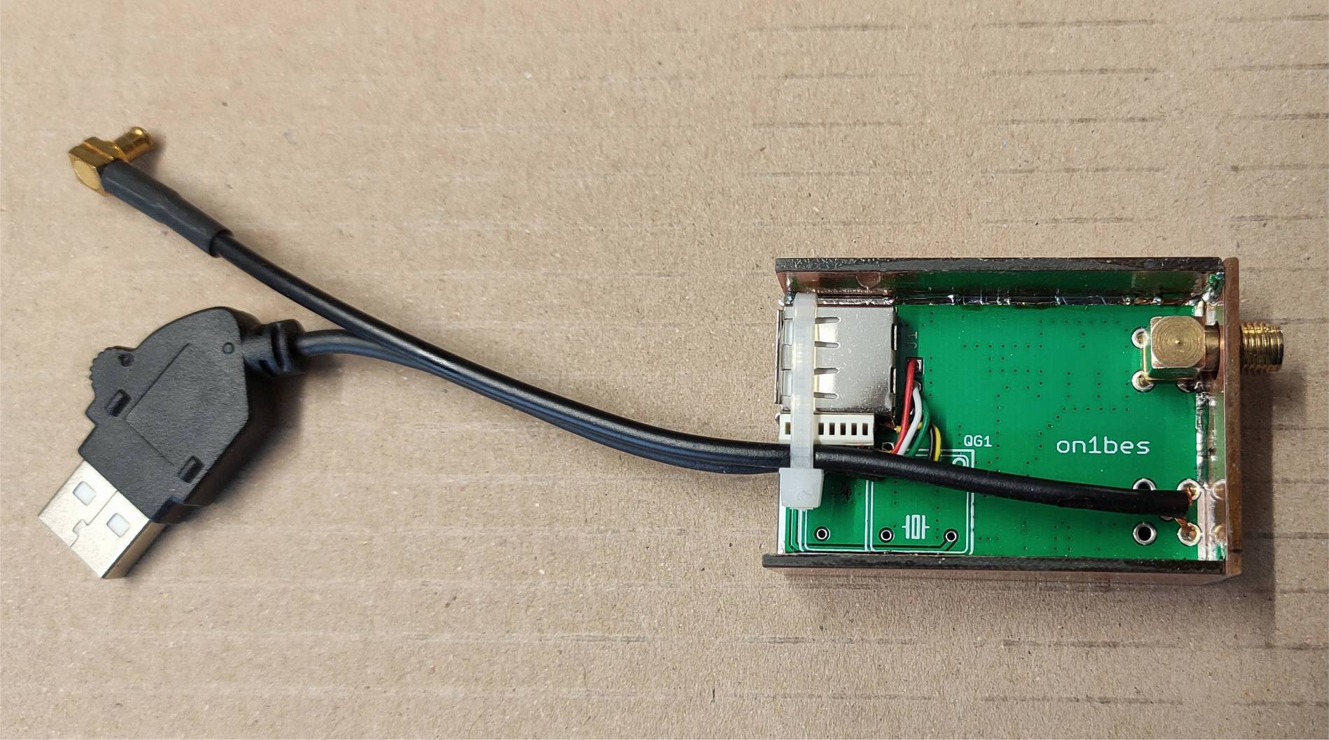
(but also ready-made, as in the photo, limited availability on request). The PCBs are unfortunately no longer available separately.
On the PCB there is 1 SMA HF input and 1 VHF output, but it has a cable with MCX type connector directly.
A cable with an SMA type connector is required on request for the V3 dongle.
It has a USB input for the SDR dongle, so you don't lose a USB port on a Laptop or PC.
operation:
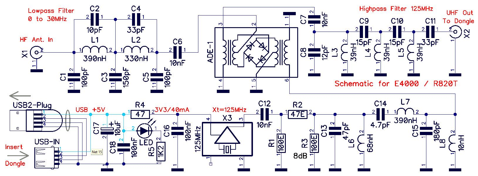
As a mixer a modern ADE-1 diode ring mixer has been used.
The oscillator for the mixer operates at 125MHz, and all types of SDR sticks can be used.The reception frequency (between 0-30 MHz) is mixed with the crystal frequency of 125 MHz. So the received frequency is added to 125 MHz.
The end result is then, if we listen from 125 Mhz to 158 MHz, then we can listen to the whole 30 MHz band, which a normal SDR dongle can receive.
In the receiver software we then set a positive shift of 125, so that from 125 MHz we get the frequency indication from 0 to 30 instead of 125 to 158.
The PCB is designed for SMD parts, and standard coils. But it is not possible to use self-made small air coils. The filter calculations were done with the program RFSim99 (in the Downloads section).
As extra shielding all around, you can saw off a few pieces of copper printed circuit board, or cut a few pictures from a tin box, and solder them around the PCB.
A normal SDR stick cannot receive anything below 22 MHz (approximately). To be able to receive something below 22 Mhz with our RTL-SDR stick, do we need a converter that converts 0-30 MHz to a frequency e.g. above 50MHz, in this case even 125 Mhz, which we can receive with a normal RTL-SDR stick. Here we choose 125 MHz as the starting frequency, so as not to conflict with the FM Radio band. Look at the Band Plan below to understand the mixer system:
Bandplan:
* An older E4000 stick receiving from 52MHz to 2200MHz, A newer R820T2 stick receives from 22MHz to 1760MHz.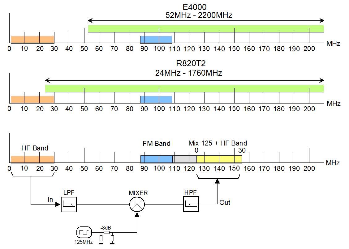
Click on the photo for larger version
An ADE-1 mixer block is used in this design:
Click on the photo for larger version
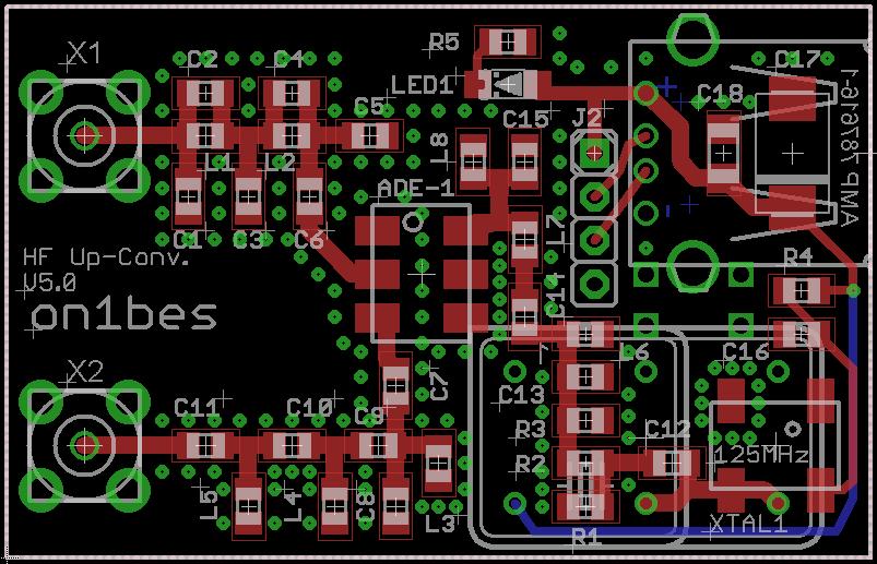
PCB and Finish:

|
|
| Model with ADE-1 Mixer | PCB V5.0 |
|
|
|
| The blue NooElec R820T2 SDR dongle | PCB Backside |
Attention: the SMA Out connector X2 is NOT placed - a short cable with the MCX connector is soldered in its place.
Characteristics of the filters:
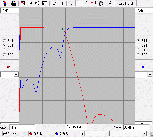
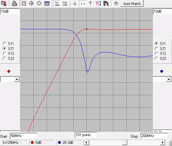
The filters are calculated with RFSim99, an old Windows7/8/xp program, but with good performance.
You must first have an installed version on XP (32 bit), and then you can simply copy the files to e.g. Win10,
otherwise the (original) installation will not work. (installed files are already in the download section).
Here you see the filter graphs in RFSim99:
 |
 |
|
The Low Pass 30MHz filter |
The High Pass 125MHz filter |
Results :
HDSDR is used as SDR software. This has the ability to mix the frequency with the 125MHz crystal on the
correct reception frequency on the screen.Immediately after construction, during testing, it was clear that there was life in the circuit.
My first test antenna was an indoor Magnetic-Loop with C tuning, enough for some basic reception.
Later versions of Up converters have been tested with a 10m EndFed antenna with good results.
Below you see 2 bands that are difficult to receive on the HF:
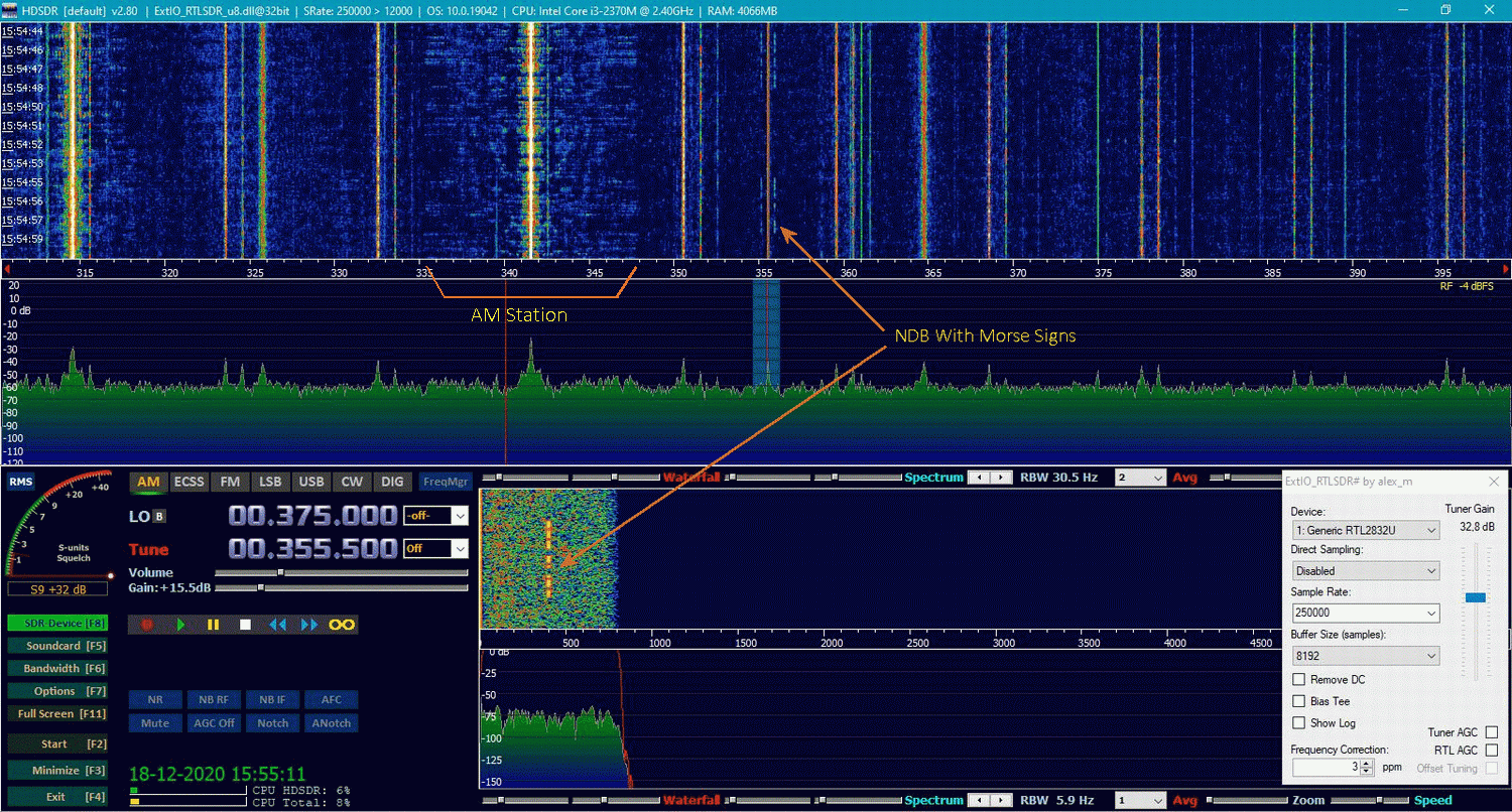
The NDB band from 380kHz to 410kHz, and the 80m HAM band from 3.5MHz to 4.0MHz.If you can receive it with your antenna, you're on the right track.
HSDR and the NDB Beacon Band 280kHz-410kHz:
Click on the photo for larger version
The station has Morse characters on the flanks, as station recognition, which you can hear when tuning.
See the big difference in bandwidth of an AM station compared to an NDB beacon station
HSDR and the 80m HAM Band:
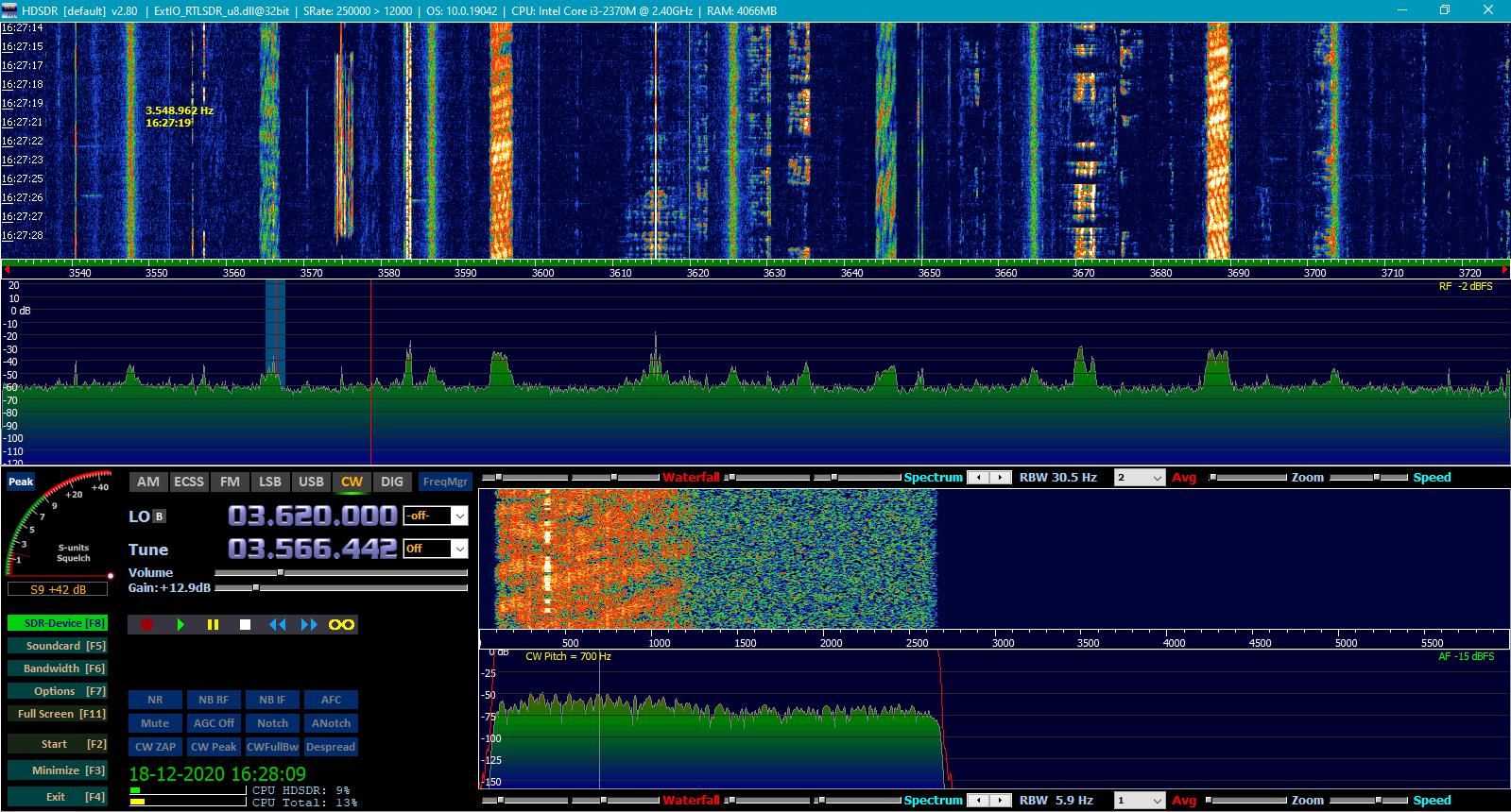
Click on the photo for larger version
The 80m HAM Band also has very narrow signals.
For even more reception results and images, see my other page: HF Upconvertor V1.0
Downloads :
RFSim99: RFSim99.zip
Het PCB en de schema's (only v3.0): Upconvertors.zip
A built and tested professional PCB has been made from this version v5.0.
If you are interested, contact me. The photos and circuit are in Upconverters.zip.
 mail: on1bes(at)Scarlet.be