|
|
 Back to Index-page |
Only
ENG version
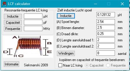 Air-coils
: they are temperature stable, and the value change
not with the frequency.
Special attention must be taken for this coils, in construction and placing on a print circuit board.
Excelent program for calculation air-coils is "LCF Calculator" which give all the needed parameters.
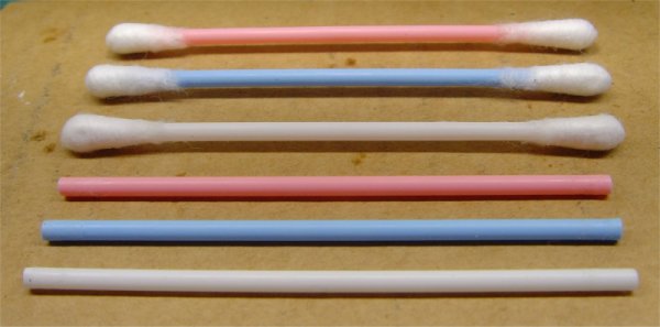
You can use smal formers of an old ball pen Ø 3mm or ear-sticks Ø 2,5mm.
Be sure you work best with some contants :
- First look what wire you have gonna to use. Good is 0,25mm to 0,6mm diameter.
- Use coil former(s) of the same diameter. Do not mix.
- Drill the needed hole(s) in line through the former - see later.
Coil formers on a ear-stick :
Made the drill tool :
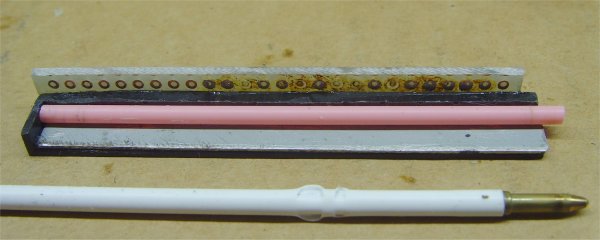
The drill tool is made of a 1/2 piece of an old Hard Disk print connector . The pin's are first removed . About in the middle lenght he is cut into two .
A small strip of a piece of print circuit board with the same amount holes is glued on top of the connector. Holes must be alligment !
Additional you need a small metal strip glued in the connector , of 0,5mm thickness to fill up the space between the former and connector.
The metal
strip filling is needed to allign the former in the
drill tool. This one is sufficient for the 0,25mm
former and for the 3,0mm former.
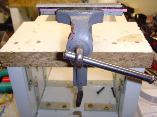
Place a former + the connetor tool in the workbench as on photo. You can tape the former to hold it on place.
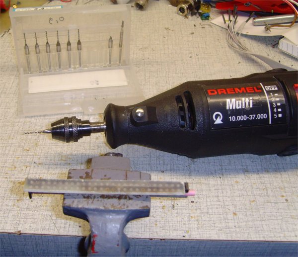
You need a drill machine (Dremel) and drill(s) of 0,8 or max. 0,9mm.
Attention: the 0,8mm carbide drill(s) brokes easy !
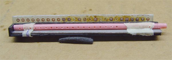
Easy drill the holes on top of the connector by stable hand , through the former.
You
can now make your first coil. Start with to put the
begin of copper wire in the first hole. Eatch winding
is about 1 cm long + 2cm for both endings.
Cut a piece of copper wire needed before you begin. Put the end of wire in the nearest hole.
You
can split the first coil form on the end and between
the next hole. Left is a coil form with 0,25 mm wire,
right are 3 coils with 0,1mm wire.
Pay attention: every time you put the wire through the hole, you have an 1/2 winding. So both end through the holes represents 1 winding.
Removing
the epoxy isolation of the wire-ends are less painless
with this Scraping Tool.
It is made of a piece of metal strip of hard steelblade.
Click on
photo for larger view
The first coil series are made with fixed lenghts of 2,54mm. Max windings is then 11 of Ø 0,25 copperwire. Max induction is about 227 nH.
The second coil series are made with fixed lengts of 5,08mm. Max windings is then 20 of Ø 0,25 copperwire. Max induction is about 479 nH.
Important: make the ends so short as possible, cut the end to max. about 2 a 3mm lenght.
This is a good start to make bigger inductors. Just use bigger or other formers.
Downloads :
LCF Calculator:
http://members.home.nl/siekmanski/LCFcalculator.exe
 mail:
on1bes@Scarlet.be
Making your own aircoils on a plastic former for HF Upconverter or Filters.
The best stable Coils are
 Air-coils
: they are temperature stable, and the value change
not with the frequency.
Air-coils
: they are temperature stable, and the value change
not with the frequency.Special attention must be taken for this coils, in construction and placing on a print circuit board.
Excelent program for calculation air-coils is "LCF Calculator" which give all the needed parameters.
You can use smal formers of an old ball pen Ø 3mm or ear-sticks Ø 2,5mm.
Be sure you work best with some contants :
- First look what wire you have gonna to use. Good is 0,25mm to 0,6mm diameter.
- Use coil former(s) of the same diameter. Do not mix.
- Drill the needed hole(s) in line through the former - see later.
Coil formers on a ear-stick :
 |
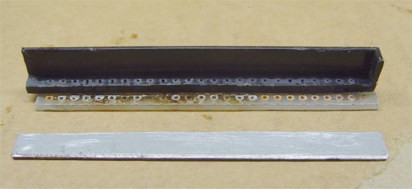 |
| Ear-sticks are Ø 2,5mm | Make first this drill tool |
Made the drill tool :
The drill tool is made of a 1/2 piece of an old Hard Disk print connector . The pin's are first removed . About in the middle lenght he is cut into two .
A small strip of a piece of print circuit board with the same amount holes is glued on top of the connector. Holes must be alligment !
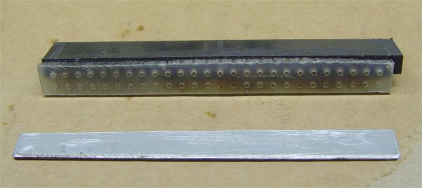
Additional you need a small metal strip glued in the connector , of 0,5mm thickness to fill up the space between the former and connector.
 |
 |
| Drill Tool with metal strip | Drill Tool and Formers 2,5 and 3mm |
 |
 |
| Drill Tool and Former in the workbench | Drill Tool and Dremel Machine |
Place a former + the connetor tool in the workbench as on photo. You can tape the former to hold it on place.
You need a drill machine (Dremel) and drill(s) of 0,8 or max. 0,9mm.
Attention: the 0,8mm carbide drill(s) brokes easy !
Easy drill the holes on top of the connector by stable hand , through the former.
 |
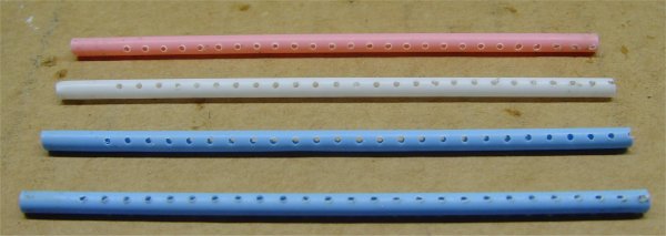 |
| Mounted former in Drill Tool | Finisched Formers |
Cut a piece of copper wire needed before you begin. Put the end of wire in the nearest hole.
 |
 |
| The first Coil on Ø 2,5mm former | Next coils-forms are splitted |
Pay attention: every time you put the wire through the hole, you have an 1/2 winding. So both end through the holes represents 1 winding.
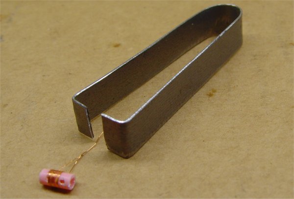 |
| Make a Scraping Tool |
It is made of a piece of metal strip of hard steelblade.
 |
 |
| Coil Series with 2,54 mm lenght | Coil Series with 5,08 mm lenght |
The first coil series are made with fixed lenghts of 2,54mm. Max windings is then 11 of Ø 0,25 copperwire. Max induction is about 227 nH.
The second coil series are made with fixed lengts of 5,08mm. Max windings is then 20 of Ø 0,25 copperwire. Max induction is about 479 nH.
Important: make the ends so short as possible, cut the end to max. about 2 a 3mm lenght.
This is a good start to make bigger inductors. Just use bigger or other formers.
Downloads :
LCF Calculator:
http://members.home.nl/siekmanski/LCFcalculator.exe
 mail:
on1bes@Scarlet.be