|
|

Back to Homepage |
Voor NL versie klik hier
Loop antennas are rewarding antennas, because they almost always WORK and are easy to make.
My goal was, among other things, to be able to receive the NDB Band with its Morse beacons between 280kHz and 410kHz. And we succeeded!.
Material and construction:
The double barrel consists of 2 strap irons of 148cm long, 2cm wide, 3mm thick, coming from the back of a wooden stacking rack.
This corresponds to a pleated circle of approximately 480mm in diameter.
They are secured at the bottom with 2x 2 bolts and nut of M6 on the lid of a sturdy gray plastic box, and the plastic box is with longer bolts (+/- 60mm) on a hardwood plank, for more stability.
A gap of 30mm has been left at the bottom between each loop end.
There was already a 4mm hole at the top of the loops, and here is a small blank PCB plate of 1.5x5cm, with 2 holes of 4mm, mounted at 35mm from each other with a nylon bolt and nut, to keep the loops 35mm apart.
The red pick-up coil is made of a single 1.5mm² electrical wire, and the circle is approximately 100mm in diameter.
The pic-up loop is soldered at the bottom on a piece of experimental PCB 22x14mm, together with the ends of the coax cable.
A 4mm hole is drilled in the middle of the PCB plate to fix the loop with a 4mm nylon bolt and nut on the platic box, exactly between the 2 loops.
All in all a nice craft 😊.

The High Band goes from about 3 MHz to 7 MHz.
The Low Band goes from about 500kHz to 4MHz.
With S2 (optional) a capacitor of 220pF is added, so that a selected frequency band can be lowered by approximately 3 Mhz.
This S2 is only needed if an even lower band than 500kHz has to be achieved.
The Tune capacitor has 2 sections that together form 300 + 200pF= 500pF, and comes from an old LG/MG radio.
The coaxial cable to the receiver only comes to the red pick-up coil, and nowhere else.
Turn the Tune knob slowly until an increase in noise is heard.
Your antenna is now tuned to maximum sensitivity.
When increasing or decreasing the reception frequency, the Tune needs to be adjusted a bit.
In the picture:
The red loop (10cm diameter) is the pick-up coil that goes to the SDR receiver.
Note, the changeover switch and the exterder switch are not visible; these were added later.
If you want good reception,
Read e.g. the article about interference and what you can do to avoid it : Interference.
Downloads: none
 on1bes at Scarlet.be
New antenna for SDR on the HF Bands (0 - 28MHz)
After years of designing and testing a MiniWhip and 4 designs, there was not much left to improve. So I was looking for something different.Loop antennas are rewarding antennas, because they almost always WORK and are easy to make.
My goal was, among other things, to be able to receive the NDB Band with its Morse beacons between 280kHz and 410kHz. And we succeeded!.
Material and construction:
The double barrel consists of 2 strap irons of 148cm long, 2cm wide, 3mm thick, coming from the back of a wooden stacking rack.
This corresponds to a pleated circle of approximately 480mm in diameter.
They are secured at the bottom with 2x 2 bolts and nut of M6 on the lid of a sturdy gray plastic box, and the plastic box is with longer bolts (+/- 60mm) on a hardwood plank, for more stability.
A gap of 30mm has been left at the bottom between each loop end.
There was already a 4mm hole at the top of the loops, and here is a small blank PCB plate of 1.5x5cm, with 2 holes of 4mm, mounted at 35mm from each other with a nylon bolt and nut, to keep the loops 35mm apart.
The red pick-up coil is made of a single 1.5mm² electrical wire, and the circle is approximately 100mm in diameter.
The pic-up loop is soldered at the bottom on a piece of experimental PCB 22x14mm, together with the ends of the coax cable.
A 4mm hole is drilled in the middle of the PCB plate to fix the loop with a 4mm nylon bolt and nut on the platic box, exactly between the 2 loops.
All in all a nice craft 😊.
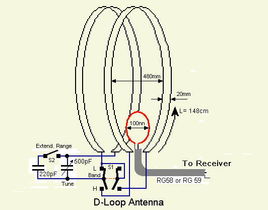
The schematic of the antenna :

Click on the figure for a larger view
Another look at the schedule:
The switch S1 toggles between the High Band and the Low Band.The High Band goes from about 3 MHz to 7 MHz.
The Low Band goes from about 500kHz to 4MHz.
With S2 (optional) a capacitor of 220pF is added, so that a selected frequency band can be lowered by approximately 3 Mhz.
This S2 is only needed if an even lower band than 500kHz has to be achieved.
The Tune capacitor has 2 sections that together form 300 + 200pF= 500pF, and comes from an old LG/MG radio.
The coaxial cable to the receiver only comes to the red pick-up coil, and nowhere else.
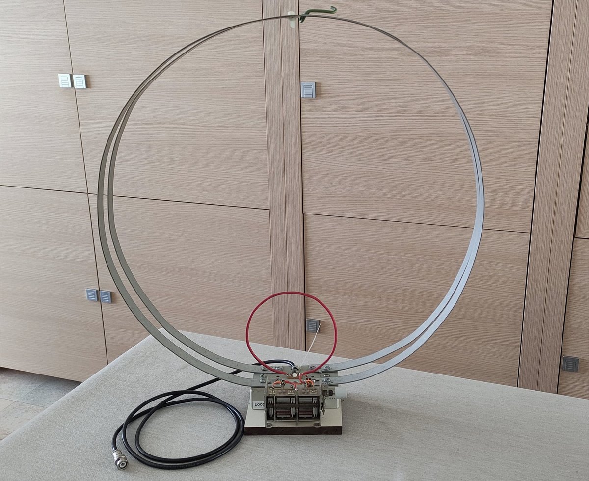
The Double Loop Indoor Antenna :
Fig.1 Double-loop Antenna with tuning capacitor

|
Click on the figure for a larger view
Gebruik:
Put your receiver e.g. at 7.021MHz (40m Band).Turn the Tune knob slowly until an increase in noise is heard.
Your antenna is now tuned to maximum sensitivity.
When increasing or decreasing the reception frequency, the Tune needs to be adjusted a bit.
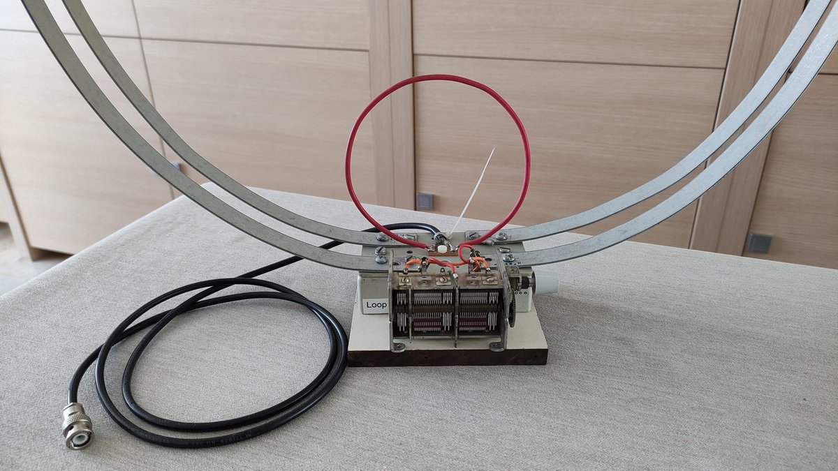
Double Loop Antenna detail :
Fig.2 Detail Loop antenna with pick-up coil

|
In the picture:
The red loop (10cm diameter) is the pick-up coil that goes to the SDR receiver.
Note, the changeover switch and the exterder switch are not visible; these were added later.
If you want good reception,
Read e.g. the article about interference and what you can do to avoid it : Interference.
Downloads: none
 on1bes at Scarlet.be