SNW Homebrew Challenge 2014 |
Voor
NL versie klik hier
Submission of Section UBA SNW 2014 - 1st place
RTL-SDR Radio HF Convertor (including Android devices)
Foreword
In this article we use a normal DVB-T
USB stick for TV reception, as a panorama
receiver on our laptop, computer, or tablet. This we "abuse" in order to receive
other frequencies with it, which it was
originally intended.
The received signal can we see
on our computer screen in a kind of spectrum
analyzer environment and the sound we can hear
in different modes like FM, AM, CW, LSB and USB.
The intention is to use HAM
software, which exists for both Windows and
Linux and Android. We use a
modified hardware driver that allows the stick
is in a sort of "test" mode, through which the
incoming antenna signals after a tuner and a
decoder in an I and a Q signal are continuously
sent to the USB port . The maximum
window width that you can see on your screen is
about 2 MHz. For example, in one
fell swoop to see the whole 2m band on your
screen. Usefull programs are HDSDR
and SDR # (SDR Sharp). With HDSDR
+ Dream is "DRM" (Digital Radio Mondiale)
possible. With SDR# there are a
variety of "plug-ins" to decode other modes. For
Android there is "SDR Touch" with the necessary
RTL2832U driver.
All this is only possible on TV sticks
containing a particular chipset. You
should therefore first sort out before
purchasing.
The usable chipsets have always a single
chip in common: a Realtek RTL2832U decoder chip,
the signal after the chip tuner for DVB-T
decodes MPEG-2, but is here in the test mode a
raw I and Q stream. Hence one also
sometimes called a "RTL stick" or "RTL-SDR"
because this chip.
Some existing RTL2832 sticks with different tuners:
 |
 |
 |
 |
| FC0013 Tuner | E4000 Tuner | R820T Tuner | R820T Tuner |
The tuner in the chipset can be
different for each type of stick and determined
the receive frequency.
The most common tuner chips are the
following:
- E4000 Elonics a tuner chip with a range of from 52 MHz to 2200 MHz (now discontinued),
- R820T or R820T2 Rafael tuner chip with a range of from 22 MHz to 1766 MHz (it is now common),
- older tuners chips are Fitipower FC0012 and FC0013 with a range from 22 MHz to 1100 MHz (with gaps!).
So
basically you can standard
with this stick
receiving VHF, UHF and SHF
partially.
But given the reception restriction
below 50 MHz on these sticks, we need a receipt
for HF converter, the HF band of roughly 0-30
MHz transforms upwards, so that we can hear the
signals at a higher frequency band (for example,
from 50 to 80 MHz) and which can receive on our
stick WEL.
The
desired design:
In this case we are going to tackle the
design of an RF converter differently than you
find in other designs that can be found
elsewhere on the Internet.
Next business for example are highly
desirable and to adapt and / or resolve:
- it must be a bit of a universal circuit for the various types of existing dongles,
- you can choose a suitable mixer crystal for the RTL stick used by you,
- the circuit must consume little power (eg for Android devices)
- it must be made integral with easy to get and inexpensive materials,
- no switching parts (relay) between HF and UHF more, as in previous designs
- 2 antenna inputs remain, one for HF and one for VHF / UHF.
Especially for Tablet or Smartphone usage:
- the circuit should be as small as possible (for android = portable use)
- an additional USB throughput feature on the converter, because a tablet usually has only one USB port,
- the power can be delivered by the Tablet or Smartphone, but also external feed is possible.
Let's look at the frequency domain and reception capabilities:
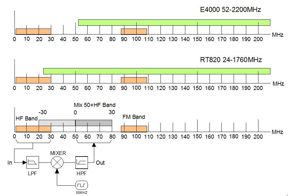
Fig. 1
Of great
importance is the choice of the crystal for the
RF mixer. This is actually
dependent on the RTL Stick used.
I still want to clearly distinguish one.
Look so sure what kind of stick that
you just got.
For the RTL stick users with E4000 tuner
(the older types):
If we look at the upper part of Figure
1, we see that an E4000 tuner only can receive
from 52 MHz. If we apply
this proposed crystal of 50 MHz to the RF mixer,
then we can after mixing, the HF band in the
segment received 50 to 80 MHz, but we lose the
reception on the first 2 MHz. That's
an important part of the HF band (0 to 2 MHz). It
is therefore appropriate for owners of an RTL
Stick with the E4000, to apply a slightly higher
crystal in order to receive the entire HF band.
There is not much margin. One
possibility is to use a cheap crystal block of
66666 MHz (from an old computer) or better
another crystal of 55 to 60 MHz. The
exact frequency does not matter. A
higher crystal can also, for example 80 MHz, but
then you come to the end of the HF band (80 + 30
MHz) after mixing in the radio FM bands that is
not the intention. Some use in
their design a 100 MHz crystal, but then the HF
band is also right in the strong FM band. A
good choice is to use, for example, a 125 MHz
crystal, but then the HF band pawl falls in the
band plane. However, that is not
very, because it was pretty quiet there, when
you do not connect the VHF antenna. The
high-pass filter must be recalculated starting
from 110 MHz, so that the strong FM band is
largely suppressed.
Here we sacrifice so either the 50 MHz
band, or a piece of plane band 125-158 MHz to
the HF band to can receive. Are
you not sure of your choice, use a 125 MHz
crystal. That always works with
any RTL stick.
For the users of an RTL stick with the
R820T:
For the owners of a R820T stick it is
somewhat easier to use a standard 50 MHz
crystal.
This stick has been receiving standard
wide from 50 MHz and there is some room to use a
different crystal, which may be between 40 and
60 MHz.
With a 50MHz crystal mixer, you receive
on HF perfect the time MSF60 channels (60 kHz)
and DCF 77 (77.5 kHz) !
In the lower part of Figure 1
shows what the intention is: the HF band passes
through a low pass filter that only the HF band
0-30 MHz pass. Then the antenna
signal is mixed with a 50 MHz crystal. At
the output of the mixer there is a 10dB
attenuator. Behind the signal goes
through a high pass filter, all below 50 MHz
blocks to remaine a pure RF signal. The last
filter is not strictly necessary, but it helps
to keep the mirror frequencies of the crystal
under 50 MHz to suppress.
Circuit:
Fig.
2
Click on it for bigger view
Clarification
and options in the diagram (for the R820T
version)
On the RF input to the first filter is
a 7 pole Lowpass filter used. C1 *
and L1 * were provided to make a 9-pole filter.
This was not necessary in practice. The
filter is asymmetrical, needed for the SA602A.
Because some values in my filters were
based on the famous "FUNcube Converter", I later
found an article from F5RCT who made firewood
of the design for the FUNcube. Many
amateurs complained about poor sensitivity at
low frequencies whith the FUNcube Converter. So
I recalculated my filters at 50 ohm input and
1500 Ohm output for the input of the SA602. And
so I have found a better filter than proposing
F5RCT.
The filters are calculated with the
program RFSim99, still proves its good service,
even in the era Win7. The
component values are optimized in order to use
as much as possible default values of the
coils.
The filter graph (input filter) is for
the R820T version:
The red line is the frequency-pass
curve. Each division is 5 MHz
wide. Begin is 1 Hz and the end is
50 MHz.
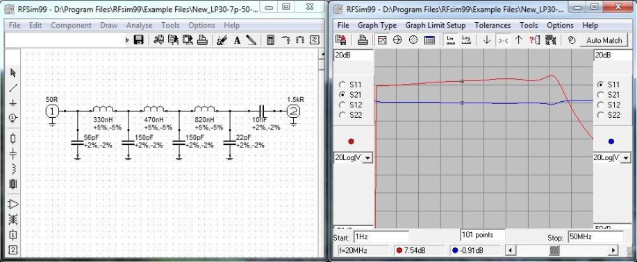 |
| The low pass input filter of 0 to 30 MHz |
Fig. 3 Click on it for bigger view
We have
chosen an active mixer with a SA602A chip. This
for 3 reasons:
1)
Because there is already a supply voltage
present (from the USB throughput) for the
feeding of the crystal block. 2) because SA602A
is a lot cheaper than for instance a SBL1 or
IE500 or modern ADE-1 passive mixer. 3) And now
because, in principle, also be a passive crystal
can be used, directly in the oscillator circuit
of the SA602A chip.
At the output of the SA602A hangs a
9-pole Chebychef Lowpass filter (optional) for
filtering of the possible image frequencies
below the 50MHz. This filter is
not really adapted to the 1500 ohm output
SA602A.
But in practice, it gave no problems
because the filter over the entire frequency
range will never be 1500 ohms and 50 ohms Out. Also
remember that the entrance of the stick is
actually 75 ohms. Of the output
filter, I have shown no graphics here.
At the end of this filter can also be
connected a VHF antenna so that switching
between HF-VHF do not need a relay. HF
antenna should then be quite disconnected.
The USB throughput provides a number of
advantages. There is a reduction
of the necessary cabling to connect the whole
and saves one USB port on the computer, or
tablet.
The USB power supply has an additional
smoothing capacitor and an extra decoupling
capacitor . This can lead to a
reduction in interference and noise on the
usually already poor USB power from a computer
or tablet.
There is a jumper after the USB connector placed. One can do two things with it: on the location of the jumper, you can feed the RF converter with an external 5V DC, or the entire HF happen off by removing the jumper. Or place a switch. For example, the RF converter remains switched off, but also the throughput for the RTL USB stick, so that in principle it is also possible to feed these externally with 5 volts.
The
crystal oscillator needs to be an active type
according to the schedule: requires
3.3 Volt . Crystal
cubes from computers usually need 5 volts. Takes
this into account. All types of
crystal cubes can fit on the board.
At the output of the crystal is an
attenuator of 10dB, otherwise the signal from
the crystal cube is much too high to mix with
the sometimes weak signals in the HF band. A
2nd reason is the following: the crystal block
produces square waves, with potentially strong
harmonics. The attenuator
partially reduced harmonics and prevents
overdriving the SA602A.
The LED in the power on the PCB is
optional and does not make much sense if the
print built in a closed cabinet. If
you do that, it is recommended that the whole in
a metal box (copper or tin) is to install.
It is a huge convenience for connecting all on just one USB port, and can stay connected to everything, and can receive both HF and VHF / UHF. By disconnecting the HF antenna temporarily, or remove the jumper, one can also receive only VHF / UHF.
Tip : For the first experiments to receive something in HF is a single insulated wire of 6 to 10m indoors or outdoors enough. You can also use your VHF antenna by de-coupling the mass (RCA plug only half insert). It is then floating and so will behave like a loose wire antenna.
The board
The PCB is double sided (1 side full mass) to have adequate shielding. But it can also be one-sided, possibly taped with some copper foil or other metal foil. I have found, however, no radiation problems in practice in earlier versions.
Some
components may be at the bottom (ground side)
and so some holes are milled to prevent shorting
to ground. Building and placing
the parts is easier if you start with the
smallest and lowest parts first and then the
larger components and the connectors.
For the right C values you can be two
solder together. For coils in
series goes that bit harder.
A crystal in SMD is mounted on the front, a crystal block is mounted on the underside as well as the chassis USB connector.
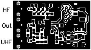
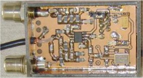
All components are on the PCB except the SMA or RCA inputs, The can be placed on a box made from copper PCB or thin around the PCB. Holes are for RCA's 6,2mm, the USB output 13mm x 6mm, 3.2mm USB cable and the OUT 3mm. The print must be around soldered to the cabinet.
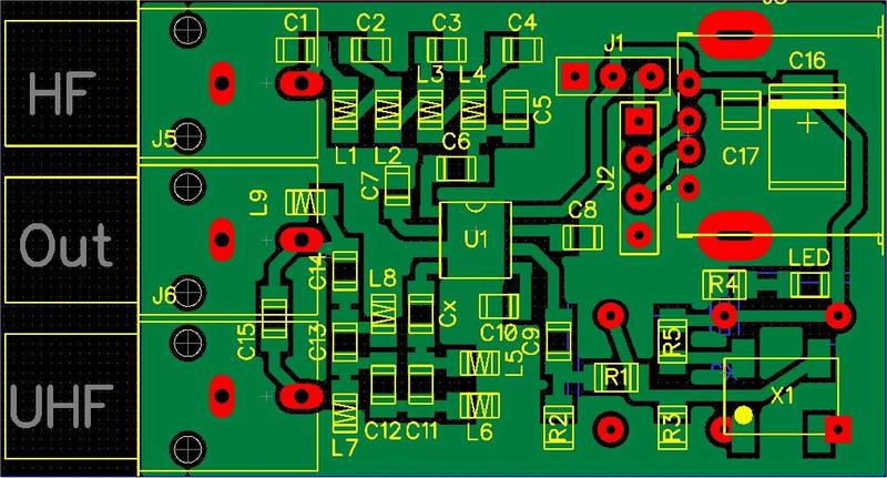
|
|
|
| The component layout | The print mask
(Older RCA Version) |
The finished
board (RCA Version) |
The central connections if it RCA plugs are by short piece of wire on the print soldered.
For the OUT jack on the PCB, I refer later in the construction and finish.
Construction and finishing
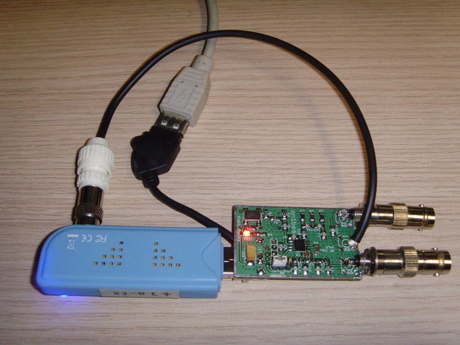
To relieve the USB port (especially on Tablet and Smartphone), the converter is connected with a short USB cable to the computer USB port . This cable is for example from an old USB mouse, or in my case a USB GSM adapter cable (to get very cheap via the Internet). Please note that sometimes you need a Mini USB cable instead of a standard type-A USB connector for your tablet.
The RTL stick itself is then plugin to the USB port on the RF converter.
In order to keep the whole a very compact, can be used as an antenna inputs RCA chassis, and this for the following reasons. In many existing HF converters, you'll find as IN and OUT , the chassis SMA connectors back. But there you are. Most of us will not have these SMA connectors in the house. If you can find them all, or buy, they are almost already fitted with a wire. They can not practically self soldering, or you need special tools. Moreover, these SMA connectors are not made to frequently connect and deconnecting. There must be another way. One possible solution is the use of cheap RCA chassis inputs .
RCA chassis used here are well suited for VHF / UHF and some of us will even know that these were also found on former TV tuners. Everyone has referred himself the choice to go with gradient plug gently into 75 ohm or 50 ohm cable to its antenna. The entrance to the RTL-Stick is always 75 ohm (TV stick!).
It is also free to use other or expensive input connectors such as BNC or MCX.
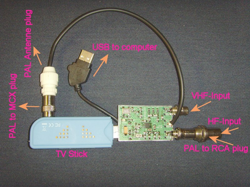
With an RTL TV stick is always a little black stock antene with magnetic foot supplied , with the right connector (MCX or PAL 75 ohms). This antene is usually tuned to about 550 MHz. Not much to begin and to use our RTL panorama receiver. This gives us the opportunity to cut the plug with the 75 ohm wire to a length of about 20 cm and connecting it to (soldering) to the output of our RF Converter PCB. See the pictures below. So we already avoid connection problems of the RF converter to the RTL stick.
To complete this story, I note that there are always improvements will be possible.
Everyone is free to do this or adapt.
Here it was just supposed to be a small, simple and inexpensive RF converter to imagine, with components fairly easy to obtain.
This design can then also compete with other commercial design.
Connections in practice
 |
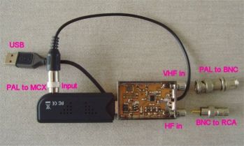 |
| The new R820T2 with MCX connector | The E4000 with
PAL connector (Older model) |
In the pictures above you can also see some useful connectors to connect an antenna of 50 ohms or 75 ohms. The blue RTL stick has a PAL to MCX adaptor needed.
Results with PC on
HF band
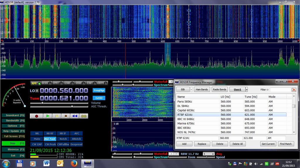
The best
program to use is HDSDR. Please
inquire about this. Installation retrieve
with a small HF antenna (single wire à 10m) are
all pretty good results. A good outdoor antnenna
is the "Mini Whip" from pa0rdt.
RTL
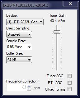
settings in "ExtIO_RTL2832.DLL"
Set the
Sample Rate to about 0.96. This gives up to a 1
MHz spectrum screen width. Set also the right
Frequency Correction of your dongle, if you
known (for callibration with a known frequency).
Set Tuner gain manually to 40 a 49 dBm to avoid
input overload.
You can use the "zoom-in" slider in the program. On HF bands, all is much closer together and it is otherwise too busy to see the signals on the screen. Also set the offset frequency of your crystal in the configuration of the program. So you can read the real frequency directly, without conversion from the alignment.
An example of RF spectrum from 0 to 1
MHz . From the clock-time channels to a part of
the Medium Wave.
The screen, however, magnified even
better with the "zoom-in" from 0 to 500 kHz.
The cursor is here on AM station RTL at
621 kHz. Also notice the fine red
line , on DCF-77 kHz.
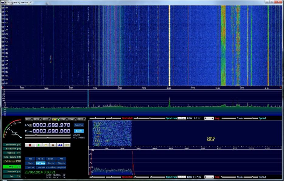
Example of the amateur 80 meter band:
The cursor is here on an LSB voice
broadcast station.
The Android story
Research
tells us that for Android devices there is not
so much available to a single "generic" DVB-T
stick to use as RTL stick on OTG USB port on an
Android device. The only programs
known to me or "App" is SDR Touch, and RF
Analyzer, both available on Google Play. There
is a trial version, with some limitations, which
you can start. You also must have
the 2nd App, the necessary RTL 2832U driver to
control the RTL chip.
All in all, it works fairly well and you
can listen to stereo FM fine with it and other
services, but you feel that the other modes as
NFM, USB and AM must be some by-developed. In
order to be able to receive on HF it is even
possible to set an offset frequency, so that you
use an RF converter under 50 MHz can listen. My
experience is that you must have an expert HF
antenna, otherwise the presence of noise and
false signals are immensely.
A disadvantage with Android Touch is
also the fact that only a window of 1 MHz can
look wide.
All in all though it is interesting to
experiment with and to look for possible
improvements.
Results with
Android (SDR Touch)
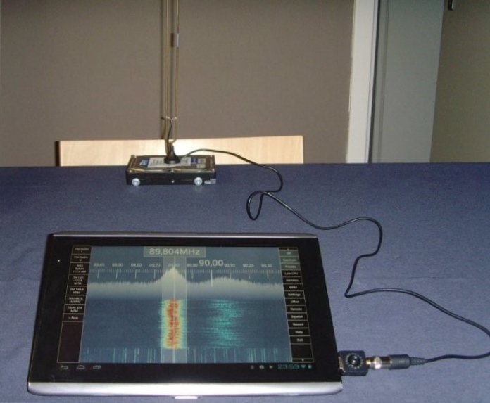
Below: the cursor is on "Radio 2" in
stereo FM.
At the back, you see a hand made "Slim
Jim" antenna for 70cm band, mounted on the
originally supplied magnet base ( Modifyed Stock
Antenna ! ).
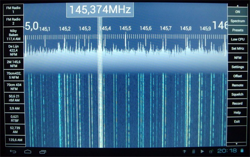
The 2-meter band in NFM:
The HF band 0 to 1 MHz (without offset) in AM:
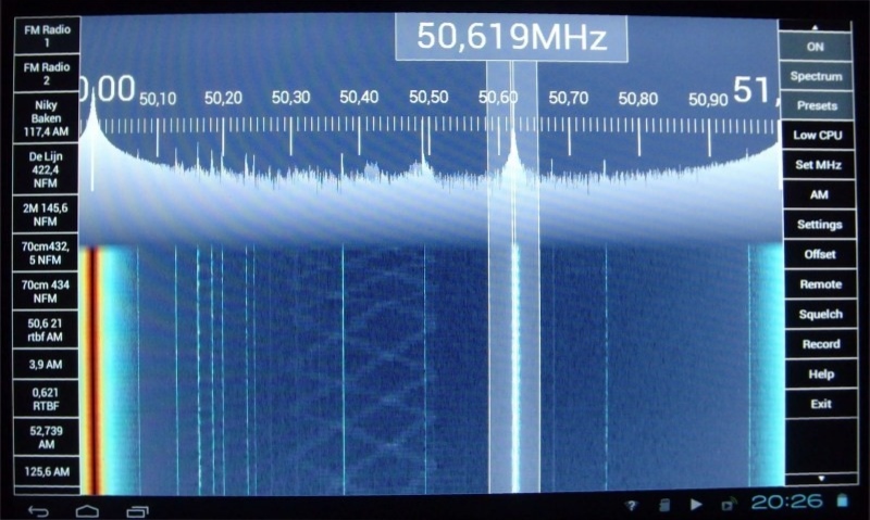
The bright colored line left on 50.00 is the crystal signal output at 50 MHz.
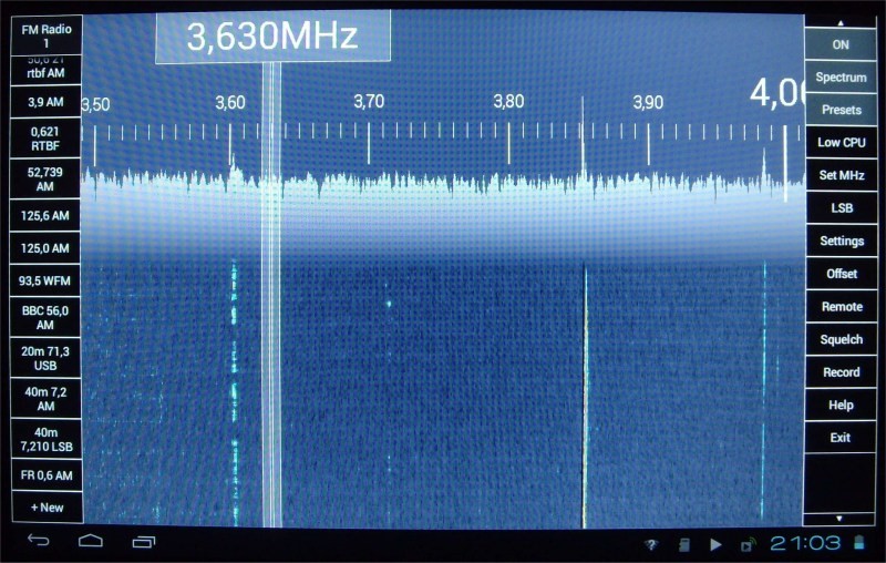
The HF 80m band in LSB:
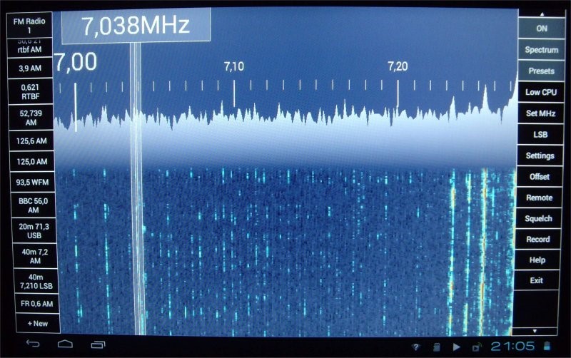
The HF 40m band in LSB:
Links and Downloads
http://sourceforge.net/projects/drm/http://www.hdsdr.de/
http://sdrsharp.com/
http://www.rs-online.com/designspark/electronics/blog/10-things-you-can-do-with-software-defined-radio
http://sdr.osmocom.org/trac/wiki/rtl-sdr
http://home.scarlet.be/on1bes/index.html
 |
|
| The new Nooelec
R820T2 with build version |

