|
 This article describes in the following diagram a handy tester for normal HC49 crystals,
but also has the ability to test a 32,678 kHz timepiece crystal.
The latter are not that easy to test because of their high internal resistance and their special properties.
A timepiece crystal oscillator requires special accurate hardware, and that has the weird feature,
that the oscillation will only start after a few seconds.
These crystals cannot usually be tested with a normal crystal tester.
If the red control LED on the PCB lights up, an oscillation is present,
after which you can also measure the resonance frequency at the frequency output.
The special thing about this design is not only in the diagram, but also in the way in which measurements are taken,
and the practical implementation of, in particular, how the coils are included in the oscillator circuit.
|
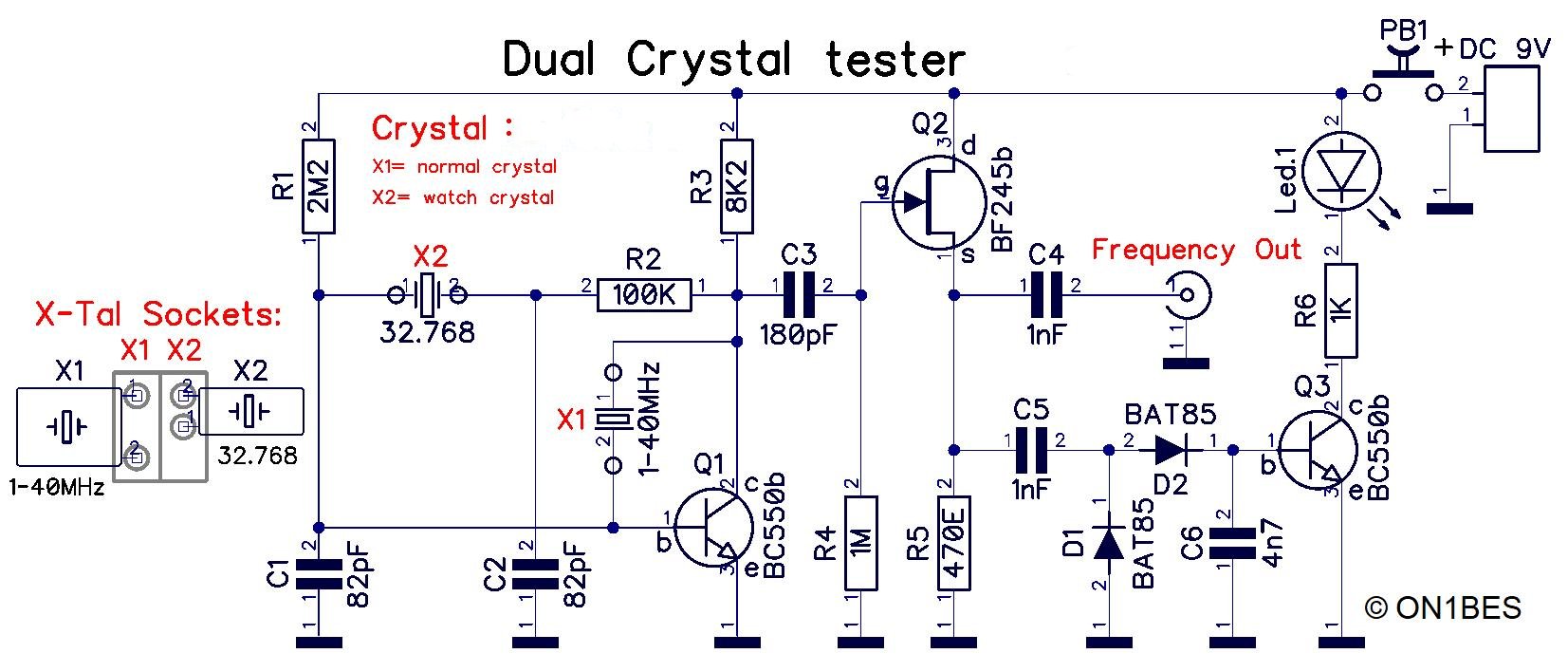
Klick on the picture for a bigger version
On the left you see the different combinations in the socket's for the crystals.
|
The circuit for regular and watch crystals:
In the above diagram you see a special version of the Pierce oscillator.
This is partly classical in structure, but has been adapted to also be able to test timepiece crystals on connection X2.
Clockwork crystals must be connected in a high-ohmic manner, so that a special adaptation to the diagram is required to start a 32,768 kHz crystal.
The strange thing is that these crystals start up only after a certain time, usually after 3 to 6 seconds or more.
Make sure that exactly the parts from the diagram are used, otherwise you have to experiment with a different transitor,
otherwise the crystal oscillator will not start, or very slowly >20 seconds.
In order to also be able to test normal crystals, a diversion is made to avoid the highly impervious part.
Please note that only on X1, normal crystals from +/- 1MHz to 40MHz (at ground frequency) can be tested.
In order to be able to measure the frequency, a FET buffer with a measuring output is provided, which may only place little load on the oscillator.
The oscillator voltage is then tapped and doubled via the diodes. The DC voltage obtained is then buffered and made visible
with an LED. The threshold voltage of the Schottky diodes is only 0.25 Volts, so that even with little signal it can be seen whether the oscillator circuit works.
The brightness of the LED also shows whether the crystal oscillates well, or only in the peripheral area.
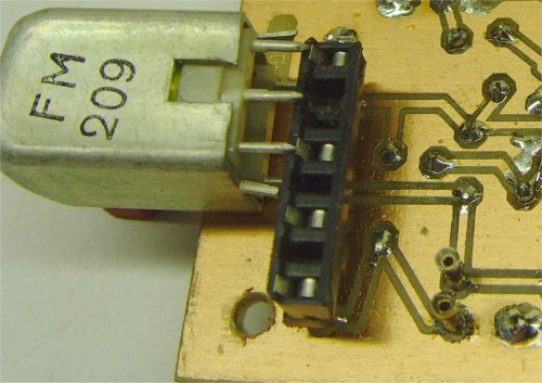
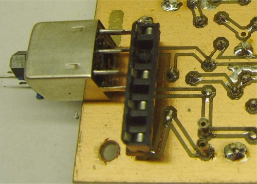
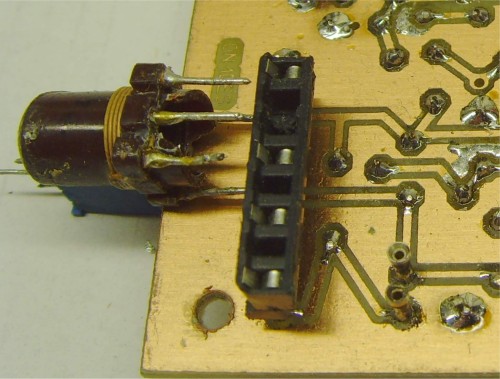
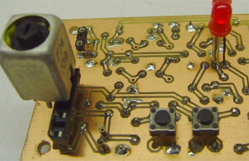
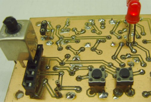
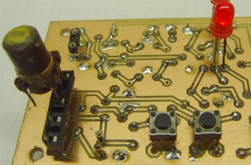
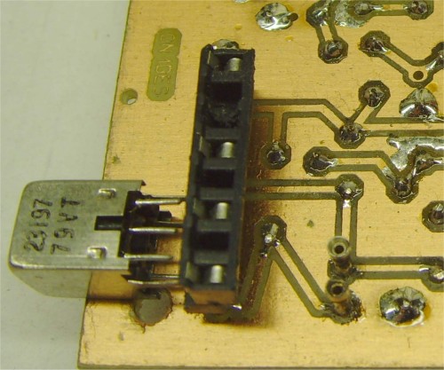
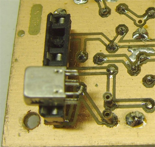
In order to be able to pierce a crystal (this with thin wires), a piece of IC-foot with twisted legs was used on X2.
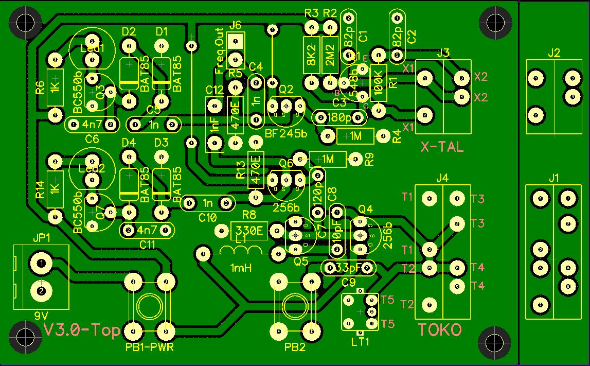
Note that a field has already been created on the proposed print (Sockets) with the deviating pin-stitch from Toko reels.
Unless with a little shift, normal IC sockets with oblique contacts will not fit.
Instead, you can use some PIN TOOLS. These are taken from a female IC Pin header (strip), gently with a hot soldering iron
pushed out, so that only the sleeve can be soldered to the print. There are on the market, headers (female pin headers) with somewhat larger holes,
where the somewhat thicker pins of a crystal fit better.
On the right-hand side of the sample print there is an extra "Socket" field that must be sawn off. Slightly larger holes are drilled on this sawn-off piece,
so that only the sleeves fit EXACTLY. The solder pins stick through, and may only fit into the print holes of the main board.
The Socket fields are placed exactly over each other, the sleeves stick through the sawn-off piece, so that they have some extra support.
Only the pins are soldered to the main print. You can glue the extra print around the sleeves after soldering with 10sec glue.
In the diagram you see the possible combinations where you can connect a crystal.
|
|

|
Types of crystals:
XT-1 : Clock watch crystal's of 32.768kHz and a keramic resonator.
XT-2 : Normal crystal's and a keramic filter.
|
|
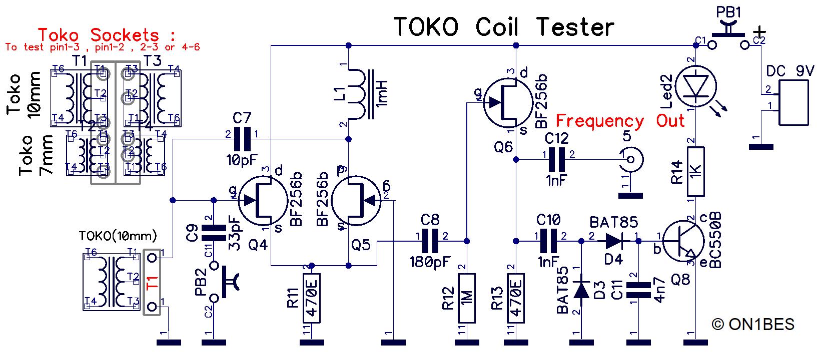
Klick on the picture for a bigger version
On the left you can see the different combinations in the socket to place 10mm or 7mm coils.
In the diagram at location T1 you can see that there is NOT a measurement between pin 1-2 or pin 2-3
These windings are usually too small to start an oscillation.
You can first measure with an ohm meter whether there is a winding present between 2 pins.
|
Schematic for the Toko coils:
It is known that Toko coils in a metal housing with e.g. a DIP meter cannot be measured properly.
The inclusion of the coil in an oscillator circuit such as this is then usually necessary.
The different types of coil shapes and pins do not make it easy to realize this, therefore a practical solution has been worked out.
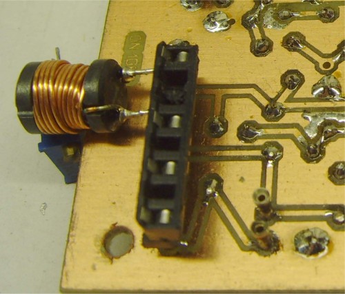
e.g. a half IC socket with oblique contacts is "sawn through" in order to be able to puncture the coil with the usually incompatible pin stitch.
A lesser-known oscillator is used in the diagram for Toko coils. That is a derivative of the Franklin Oscillator.
To test a TOKO for its true resonance frequency, it is necessary to find an oscillator that
a parallel circuit accepted at its entrance. However, there are not that many.
Most oscillators (including Pierce and Colpitts) use a capacitance in series with the coil to be measured, and they will resonate differently with a TOKO,
which often already has an internal capacity parallel to the coil.
Moreover, a TOKO, which has NO internal capacity, will of itself already form a capacity with the coil windings,
and that would affect the resonance frequency unfavorable.
The oscillator in the diagram uses a cascade circuit of 2 FETs with a common source connection (source follower).
The only frequency-determining component is the TOKO coil, with or without internal capacity.
(the capacity between the Gate and the Drain is only for the feedback, and should be kept as small as possible, and minimally influences oscillation)
This gives a better indication to see at which frequency range the coil can be used.
If the TOKO (at sight) has no visible capacity, the coil is first measured in the circuit.
An oscillation will often already take place without additional attached capacity.
If there is no oscillation, you can switch on an extra capacity of 33pF with the push button.
If oscillation then takes place, and this is measured with a frequency meter, this is a reference
on which the TOKO can be used. Therefore measure the TOKO with and without added capacity and compare the frequencies.
The oscillator voltage is first buffered with a FET and then tapped and doubled.
The DC voltage obtained then switches a red LED via a transistor.
The threshold voltage of the Schottky diodes is only 0.25 Volts,
so that even with little signal it can be seen whether the oscillator circuit is working.
You can tell by the brightness of the LED if the oscillator frequency of the coil is of good quality.
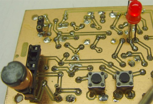
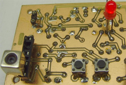
In order to be able to puncture the coil, a piece of sawn-off ic-foot with oblique contacts was used.
Or on my new print version, as above, a Socket field has been made with customized PIN distances for large or small Tokos.
Note 1: the measured frequency can be used to determine whether a Toko is suitable for a mid-frequency 455kHz or 10.7MHz or another MF.
Of course, the frequency will deviate a little, if the Toko core is screwed in more or less.
Note 2: this Toko tester will work (oscillate) in 95% of the cases, when measured between the extreme pins 1-3 or pins 4-6.
Most windings between pin 1-2 and pin 2-3 are usually too small to achieve an oscillation.
In this case, the winding can first be measured with an L-C meter, and the resonance frequency can be e.g. be calculated with an "LCF calculator" (in the Download).
As a fixed capacitor in the circuit, take C9 of 33pF, if PB2 is pressed.
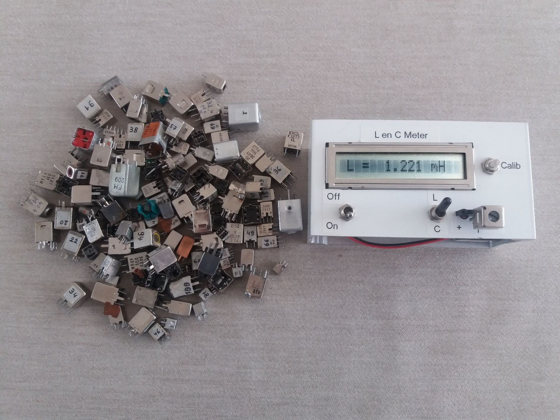
For this article about 100 Toko coils are determined here where there is a winding on the pins, and then
the windings are measured with an L-C Meter (also to be found on my Website). This way you get an idea about the size of the induction of a winding,
and you can determine a frequency usage range: large induction value = small resonance frequency, and small induction value =
large resonance frequency. All these values and types of Toko coils with their characteristics can be found here in an Excel table as a download.
Note that maybe not all Toko coils will indicate an oscillation or resonance frequency.
In my test of 12 of 100 selected TOKO coils, with and without internal capacity, the measured inductance on pin 4-6 was between 300nH and 1343 mH.
Of these, around 4 TOKOs did not want to oscillate. But with the measured induction and the 33pF capacity in parallel,
the resonance frequency can still be determined via the LCF Calculator.
|
|
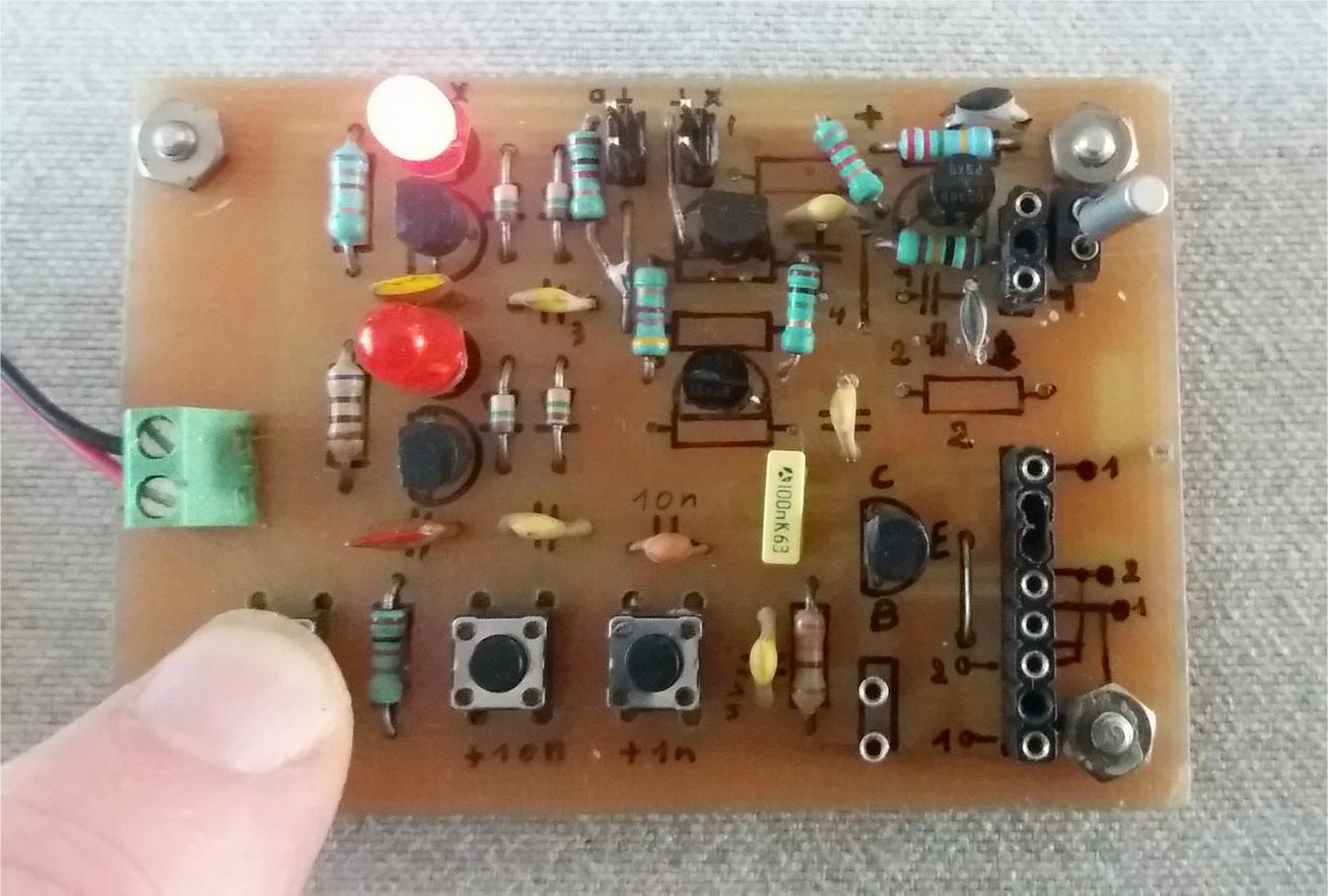
Component side V2.0 (measurement of a Clock watch crystal)
 |
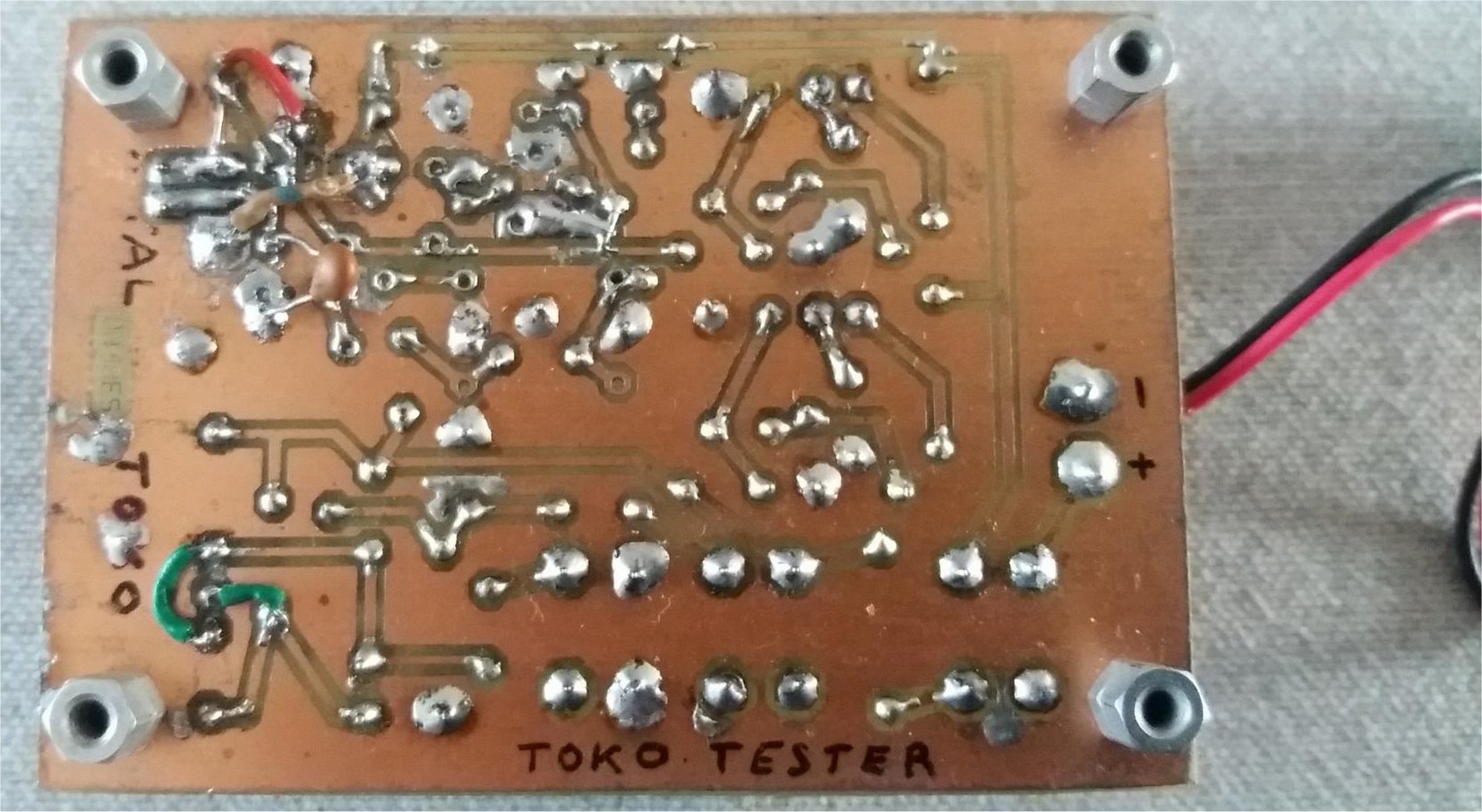
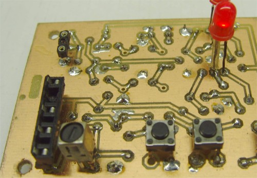
Solder side v2.0 (attention: this a old test PCB)
 |
New PCB Layout v3.0 5x7,5cm
|
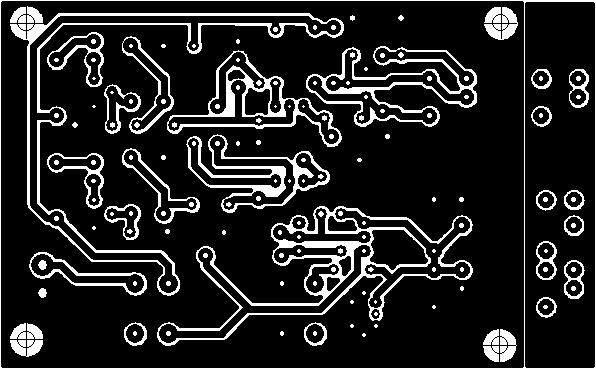
New PCB Mask v3.0 5x7,5cm (mirrored)
|
|
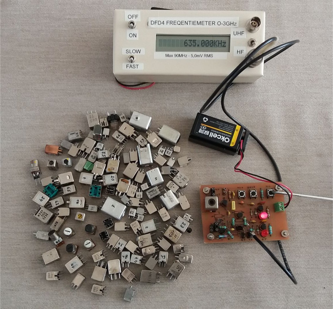
Resonance frequency measure with Frequency meter
|
Measure induction value with LC Meter
|
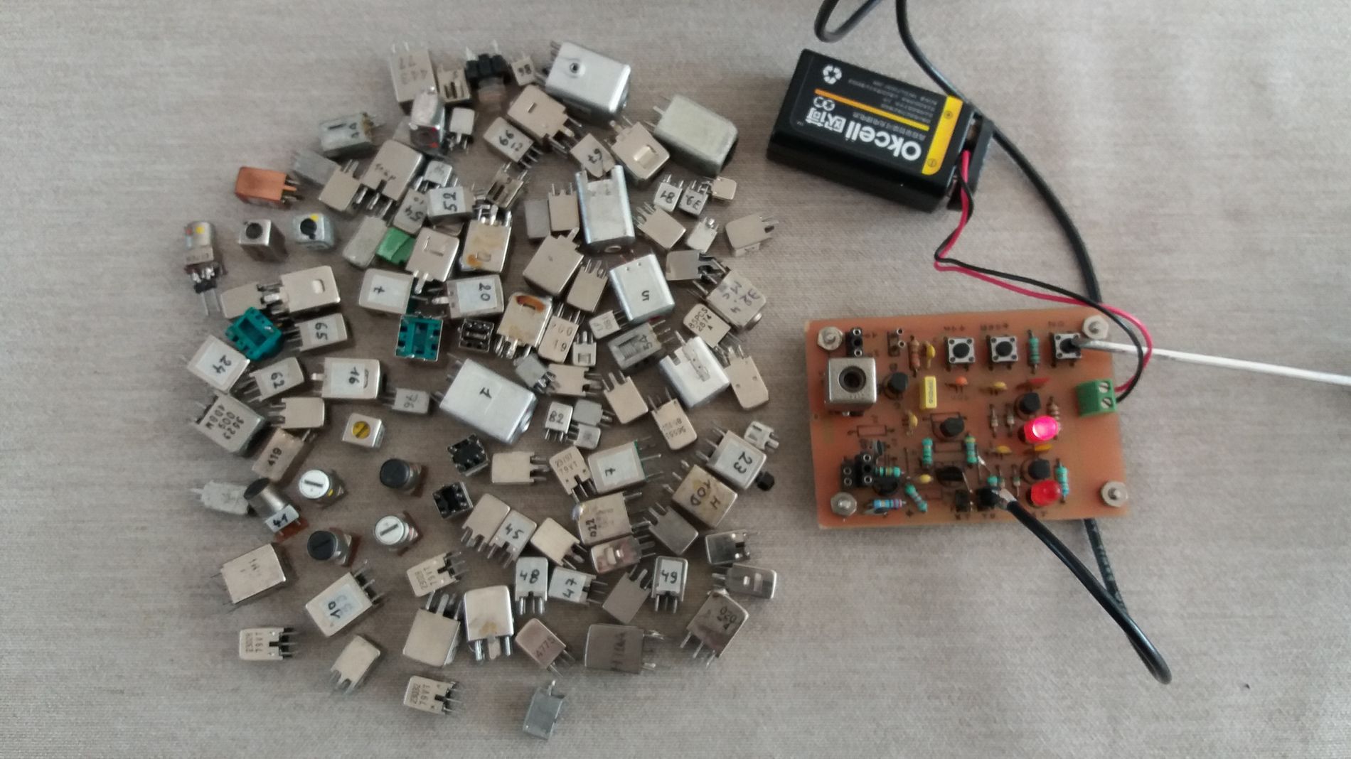
A somewhat older DFD4 frequency meter has been used above.
The TOKO print circuit board on the photo is an older version.
You can also find the L-C meter (right) on my website.

 on1bes at Scarlet.be




 on1bes at Scarlet.be


