|
|

Back to Homepage |

Voor de NL versie klik hier
For the Basic Mini-Whip Antenna 2016 click here
However, for a practical implementation, it is not always that easy to find a suitable housing for outdoor mounting.
You sometimes see jars, boxes, tubes and other peculiar housings, which must also be weatherproof and waterproof.

Click on the figure for a larger view
The layout of the antenna print and the PWR splitter : note ! on the photo,the isolation transformer is NOT placed.
The cover caps are 22mm long and 36mm in diameter. These must be glued for watertightness.
For the lower cap you can also use an internal PVC stopper of 18mm, which is then pushed INTO the tube, and does NOT have to be glued.
Insert a piece of insulating foam in the head, and optionally the bottom of the tube, so that the Antenna PCB cannot move.
As an antenna connection, e.g. it is better to omit a BNC connector due to moisture problems. Instead, the cable can be connected to the antenna board, with e.g. a solderable print terminal block can be connected, as shown on the construction drawing in Fig.2, or if possible, soldered directly.
Drill a 6mm hole in the center of the bottom cover to feed the coaxial cable to the print terminal block on the antenna print.
As an extra, at the bottom, between the antenna PCB and the cover, you can slide a piece of 5/8" PVC tube over the cable in advance, to keep the antenna print in place, at some distance from the bottom.
Slide the whole at the bottom, in the 32mm tube, up to the 5/8" thrust ring, in order to clamp the antenna print. Clamp everything at the bottom with the (internal) cap of 18 mm, to seal the pipe watertight.
Important: due to the use of an aluminum bracket (Fig.2) the PVC pipe is free in the air, to be mounted on a mast with the bracket part.
It is important to mount the antenna section ABOVE a metal mast, and not next to it. The antenna section must be in the open air in order to receive the radio waves from all sides.
On the left the layout of the Antenna PCB - On the right the layout of the power supply PCB
The power supply board with signal splitter The power supply PCB fits e.g. in a 19x19 mm piece of square aluminum tube from the hobby market. The length will be a bit different for everyone, depending on the BNC chassis. One head end of the tube is folded closed after sawing off 3 side pieces of the tube (see photo on the right). A hole (12.5 mm) is drilled on the head of this to allow the BNC chassis wire to protrude to the outside. Usually it also needs to be filed out a bit to fit.
Important: Where the PCB bottom with copper side enters the tube, slide a 0.3 mm thick, cut-out stiff piece (blister) of plastic or skin in the tube, so that the copper side cannot make contact with the bottom of the aluminum tube.
If you have mounted an LED, you can drill a 5 mm viewing hole in the tube at the appropriate place.
From the BNC chassis to the antenna print, use a long coax cable with a BNC plug on one side.
The coaxial cable from the power PCB, to the SDR receiver or to an HF Up-Converter, is soldered on the contacts of the power supply PCB.
You can close the open head side of the square tube with a square PVC cap from the hobby market.
The cable to be soldered first goes through a drilled hole of 6 mm, in the middle of the PVC cap (see photo).
The cable of the power supply passes through a drilled hole of 2.5 mm, through the hood (see photo).
Change the 9V connector to another one if you are going to use a mains adaptor.
For a test of this antenna, check out my website for the HF Mini Whip Antenna.

If you want good reception, the following is very important :
This is an OUTDOOR antenna. Do not use them indoors. The electrical disturbance indoors is simply too great.
Exactly follow the connections in the figure to suppress the antenna. You can see that there is an extra ground wire running directly from the PCB to the antenna mast.
At the bottom of the antenna mast, the mast is grounded again.
Read the article about interference and what you can do to avoid it : Interference.
Downloads:
PCB-layout download hier: MiniWhip1.2.zip
References (Maybe some are already off-line):
PA0RDT-Mini-Whip Antenna
PA4NIC MiniWhip-pagina.html
Technical pages :
DL1DBC whip/Article_pa0rdt-Mini-Whip
PA3FWM projects/miniwhip/
PA3FWM Technotes Grounding
Note: There are no Gerber files of the PCBs. My program cannot generate it.
 on1bes at Scarlet.be
For the Basic Mini-Whip Antenna 2016 click here
Improved Mini-Whip antenna in SMD verion 1.2 (10kHz-28 MHz)
New design with new schematic in SMD Version
There are already countless designs and versions of the MiniWhip antenna (see my previous article --> Basic Mini-Whip Antenna).However, for a practical implementation, it is not always that easy to find a suitable housing for outdoor mounting.
You sometimes see jars, boxes, tubes and other peculiar housings, which must also be weatherproof and waterproof.
Here is a modern variant, with SMD mounting, for better operation, and at the output, a suppression blocker in the signal path.
Due to the extensive miniaturization, we can use a simple construction.
This version is a version that fits in a piece of white sanitary PVC pipe (32mm external), with 2 end caps for sealing.
The internal diameter of the PVC pipe is 28mm.
The Mini Whip can be fully retracted into this (Fig. 2).
It is now much easier to clamp the whole outside, on a metal pole or a PVC pole with 2 standard plastic brackets or clamps.
** Attention: when using a metal mast, the PVC part containing the antenna must protrude ABOVE the metal mast.
The Antenna part itself is 75x27mm, the total print is 147mm long, on single sided print.
The schematic of v1.2 the antenna and the power supply :
Click on the figure for a larger view
A quick look at the schedule:
The copper antenna is here designed as a kind of coil and forms a pure capacitance (4 to 6pF) with the surrounding air.
This is coupled to the gate of an SMD BF998 dual-gate MOSFET transistor with a very small input capacitance (+/- 2 pF).
This high input impedance FET is coupled to a BCX56 Power HF transistor, which turns it into a low impedance down to 50 ohms.
The output of this transistor goes via a decoupling capacitor of 100nF via the antenna cable type RG58 (50 ohm) to the power splitter.
As an antenna cable from antenna to the power splitter, it may also be a cheap RG59 TV cable of 75 Ohm.
The DC power supply (9-12V) goes via the same coaxial cable to the antenna board, and is used for AC on both sides.
decoupled by a choke and a power splitter.
On the power supply board, the receive signal is separated from the DC supply by a decoupling capacitor of 100nF.
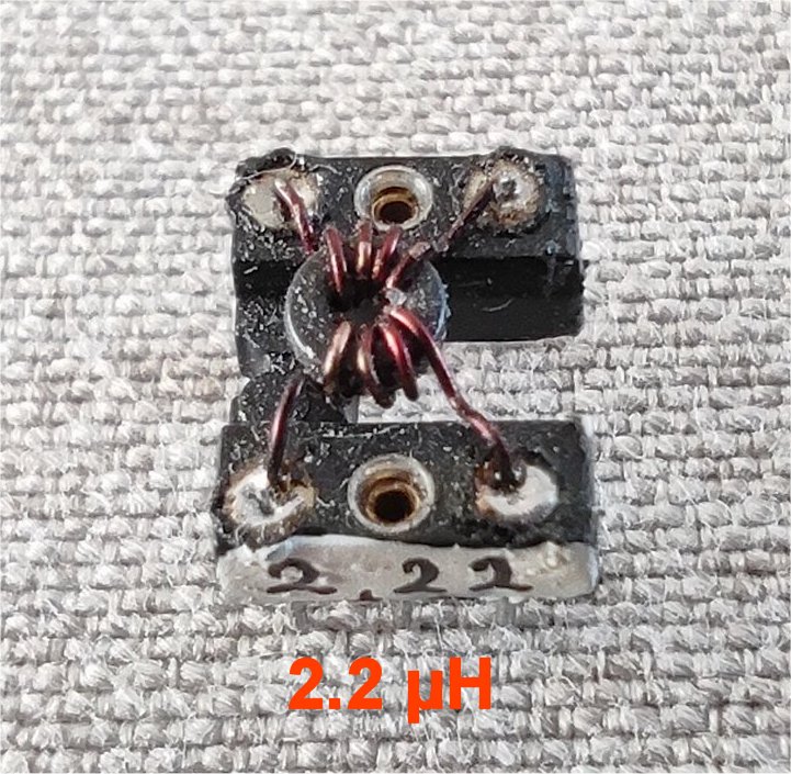
New in this version is a mini isolation transformer (TCE-4), on the power supply board,
which isolates the receive signal from the cable ground that goes down the road to the receiver.
Actually it is a homemade mini toroid with 3wdgn primary and 4wdgn secondary (see photo).
The cores I use come from an RJ-45 network connection on an old computer board, and they are very suitable for the low HF bands.
But just to be sure, measure the properties for HF with a MiniVNA or NanoVNA,
because you can't adjust the windings yourself with this one.
It is important that the power supply comes from a 12V battery, or from a 9V mains adapter WITHOUT earth.
The cable that goes from your SDR receiver to the power supply board is disconnected from the power supply at the RF terminal,
so that the ground of your SDR cable,
cannot reach the antenna board. Note the separate ground sign at RF Out.
How the antenna works:
The strength of the antenna signal is actually the difference between the signal on the antenna plate and the ground plane on the PCB.
Because there is little ground plane on the antenna AMPLIFIER PCB, it is important that the antenna board is grounded at the EARTH POINT U1,
with a separate wire to a metal mast, or with a PVC mast, directly to a metal pin in the ground.
With a metal mast, this in turn is grounded at the bottom with a pin to the ground.
 The diagram also shows that an extra isolation transformer has been included in the power supply.
TCE-4 is NOT a commercial balun type, but you can make one yourself (see opposite).
The prim.= 3wdgn and the sec.= 4wdgn. The inductance value of the sec. coil is 2.2 µH (4wdgn).
In principle this can be omitted, but there is a chance that the interference level on the antenna will be a lot higher.
The intent is to decouple the receiver-ground so that the antenna cannot receive interference from the receiver across the cable sheath.
Many of these 'special' parts are available from Aliexpress.
The layout of the antenna print and the PWR splitter : note ! on the photo,the isolation transformer is NOT placed.
Fig.1 Antenna + Power and Splitter

|
|
Fig.2 Drawing of the 32mm PVC pipe and cover caps - inside you see the antenna PCB 
|
Click on the photo for a larger view
The total antenna print is 146mm long, and fits into a piece of white PVC pipe that is 180mm long, and 32mm external diameter.The cover caps are 22mm long and 36mm in diameter. These must be glued for watertightness.
For the lower cap you can also use an internal PVC stopper of 18mm, which is then pushed INTO the tube, and does NOT have to be glued.
Insert a piece of insulating foam in the head, and optionally the bottom of the tube, so that the Antenna PCB cannot move.
As an antenna connection, e.g. it is better to omit a BNC connector due to moisture problems. Instead, the cable can be connected to the antenna board, with e.g. a solderable print terminal block can be connected, as shown on the construction drawing in Fig.2, or if possible, soldered directly.
Drill a 6mm hole in the center of the bottom cover to feed the coaxial cable to the print terminal block on the antenna print.
As an extra, at the bottom, between the antenna PCB and the cover, you can slide a piece of 5/8" PVC tube over the cable in advance, to keep the antenna print in place, at some distance from the bottom.
Slide the whole at the bottom, in the 32mm tube, up to the 5/8" thrust ring, in order to clamp the antenna print. Clamp everything at the bottom with the (internal) cap of 18 mm, to seal the pipe watertight.
Important: due to the use of an aluminum bracket (Fig.2) the PVC pipe is free in the air, to be mounted on a mast with the bracket part.
It is important to mount the antenna section ABOVE a metal mast, and not next to it. The antenna section must be in the open air in order to receive the radio waves from all sides.
On the left the layout of the Antenna PCB - On the right the layout of the power supply PCB
 The Antenna PCB and AMP (dimensions are in mm) |
 The power/splitter PCB (dimensions are in mm) |
 Photo of the power supply PCB and cable to receiver |
 Photo of PWR splitter and cable to the receiver |
Click on the photo for a larger view
The power supply board with signal splitter The power supply PCB fits e.g. in a 19x19 mm piece of square aluminum tube from the hobby market. The length will be a bit different for everyone, depending on the BNC chassis. One head end of the tube is folded closed after sawing off 3 side pieces of the tube (see photo on the right). A hole (12.5 mm) is drilled on the head of this to allow the BNC chassis wire to protrude to the outside. Usually it also needs to be filed out a bit to fit.
Important: Where the PCB bottom with copper side enters the tube, slide a 0.3 mm thick, cut-out stiff piece (blister) of plastic or skin in the tube, so that the copper side cannot make contact with the bottom of the aluminum tube.
If you have mounted an LED, you can drill a 5 mm viewing hole in the tube at the appropriate place.
From the BNC chassis to the antenna print, use a long coax cable with a BNC plug on one side.
The coaxial cable from the power PCB, to the SDR receiver or to an HF Up-Converter, is soldered on the contacts of the power supply PCB.
You can close the open head side of the square tube with a square PVC cap from the hobby market.
The cable to be soldered first goes through a drilled hole of 6 mm, in the middle of the PVC cap (see photo).
The cable of the power supply passes through a drilled hole of 2.5 mm, through the hood (see photo).
Change the 9V connector to another one if you are going to use a mains adaptor.
For a test of this antenna, check out my website for the HF Mini Whip Antenna.
Grounding a MiniWhip antenna
If you want good reception, the following is very important :
This is an OUTDOOR antenna. Do not use them indoors. The electrical disturbance indoors is simply too great.
Exactly follow the connections in the figure to suppress the antenna. You can see that there is an extra ground wire running directly from the PCB to the antenna mast.
At the bottom of the antenna mast, the mast is grounded again.
Read the article about interference and what you can do to avoid it : Interference.
Downloads:
PCB-layout download hier: MiniWhip1.2.zip
References (Maybe some are already off-line):
PA0RDT-Mini-Whip Antenna
PA4NIC MiniWhip-pagina.html
Technical pages :
DL1DBC whip/Article_pa0rdt-Mini-Whip
PA3FWM projects/miniwhip/
PA3FWM Technotes Grounding
This antenna is great for use with my SDR HF UP-convertor :
SDR Up-converter v3.0 XT_125Note: There are no Gerber files of the PCBs. My program cannot generate it.
on1bes at Scarlet.be