|
|

Back to Index-page |
First Mini Whip antenna in SNW-UBA ?
Update 2021: New techniques, new insights
Test of a basic Mini Whip antenna (PA0RDT) for HF Frequencies from 10kHz to 28MHz
After an intense search on the Internet for a simple antenna for HF-SDR reception (10kHz-30MHz), I came across this Mini-Whip from maker PA0RDT, which can be found in many variations. The boys from the Dutch Unief Twente also use this antenna for their Web-SDR. Since it is an active antenna, I was quite skeptical, because my previous experiences in this kind of antennas were rather disappointing.In this article you will read some more insights and techniques. In the "Slim Line" version, elsewhere on the site, this is less the case.
About 30 years ago, there was once a free print from Elektor, with which you could make an active (indoor) antenna, with a sliding blade. That wasn't really a success, and the whole thing ended up in the junk box. I didn't really know how it worked at the time, and hadn't heard of any malfunctions in the house at the time. After it was exactly recreated according to Elektor, it didn't work very well either.
Conclusion: you must have seen some of the theory of the Mini-Whip to understand it.
Let me put it this way: this whip antenna no longer works indoors these days. 30 to 40 years ago.
The electrical interference radiation indoors is simply too strong these days. More on this later.
But yes, I had now started building my own antenna, a "Mini-Whip". I thought, let's get it right right away. So I made a PCB design with a PCB design program, and later also drew a schematic in there, and after that the PCB result was printed, and a PCB was made of it.
The basic scheme:

Click on the drawing for a larger version
The schedule is as you can find many on the internet. There is almost no variety. The actual antenna is a copper plate of at least about 3x4 cm.
This picture represents a capacitance of about 3 to 5pF, and is single-sided. This copper pad is coupled to a J-FET Type No. J310, which has a very small input capacitance of about 2pF. This is also a low noise transistor amplifier. The next stage with a transistor, type TRW80181, is an old VHF RF transistor, which was used in cable TV amplifiers.
Another good HF/VHF transistor is also good (eg 2N5109), as long as it can draw around 110mA emitter current.
The main task of this 2nd transistor is to form a high/low impedance converter with the coax cable to the receiver.
The power is supplied over the coax cable, from the power supply to the antenna pcb, the signal is decoupled from the power line via a choke coil.
Although it is also possible without (flying setup), it is best to make a small print. That is a bit more stable and clearer.
Between the antenna PCB and the power supply PCB you can use either a 75 or 50 Ohm coax cable with BNC plugs, but for outdoor use these are not recommended due to moisture problems, and a BNC is not really made to send a lot of current through it.
A printed terminal block is preferred, and you can connect the coax cable directly to it.
On the power supply side, between the power supply PCB and your (SDR) receiver, use a piece of coaxial cable (+/- 1m), which is soldered directly to the power supply PCB on 1 side. The other side can be a BNC, or any other connector that fits your receiver.
On the power supply PCB :
Power supply: Pad1= +9V, Pad2= GND.
(Pad3= signal from coax mid-core, Pad2 and 4= GND).
The impedance that the receiver sees is estimated to be about 100 Ohms.
The PCBs: HF PCB and power supply PCB - Replace the BNC with a terminal block

HF PCB design - Replace the BNC with a terminal block |

Photo HF PCB of the built HF PCB |

The power supply PCB design |
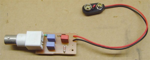
Foto power PCB |
Click on the drawing for a larger version
Connecting the power supply to an HF-Upconverter and SDR receiver:
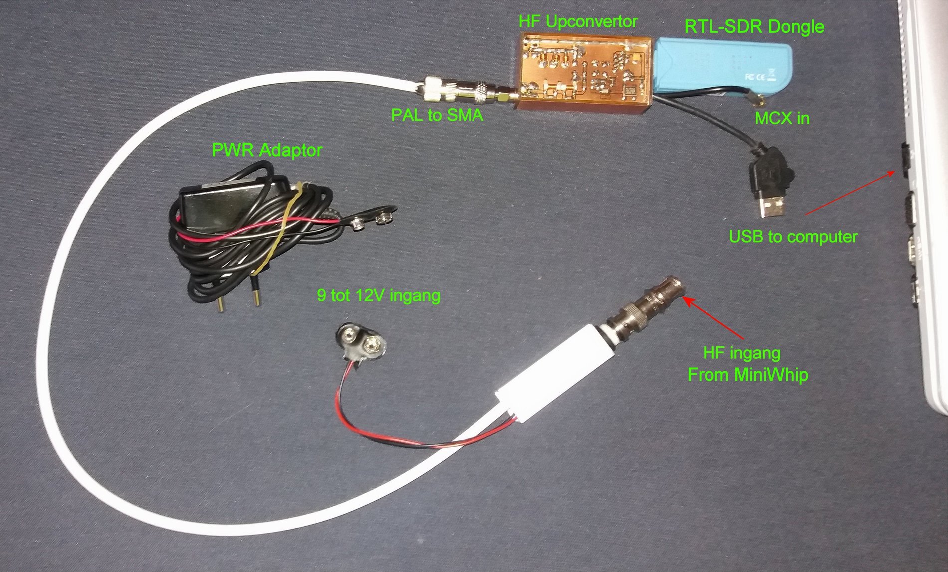
What should we know about a MiniWhip?
There are 2 types of antennas for 2 types of radio waves : magnetic and electric. These are rotated 90° from each other.
The MiniWhip (any whip, or rod) is sensitive to electrical waves in the air.
A (Magnetic) Loop antenna or Ohm antenna is sensitive to magnetic waves in the air. We assume that both antennas can work equally well.
Where does a MiniWhip work best?
A MiniWhip works best outside and away from buildings. To understand this we need to look at some physical features.
Features of a MiniWhip
The antenna surface of a MiniWhip is usually a copper plate, but can also be a whip or telescopic extendable, and forms a very small capacitance with the air.
Behind the antenna surface is an amplifier and an impedance matcher to the power cable.
The power to a MiniWhip can be done on site with a battery, or else via the antenna cable.
Disruption in the home and beyond
We have to realize that in the city, for the last 30 to 40 years, we in our houses, living in an enormous electromagnetic radiation, coming from different devices, such as (dect) telephone, computer(s), VGA, LCD and baby monitors, almost all mains plug power supplies, Fluorescent lamps, LED lamps, WiFi and many other electrical sources of interference.
Nowadays you are still out of the house with switching solar panels and electric fence guards.
This radiation is even present on our entire light grid, both in the power wires and in ground wires.
Remember: ANY wire, long enough, will form a jamming antenna in your home for a sensitive receiver.
Receiving weak signals
So we live in fairly strong electromagnetic radiation, which prevents other weaker signals from outside to be received with a sensitive receiver such as e.g. an SDR receiver.
They are there, but they are completely pushed away by the interference radiation in the house, which is stronger.
A receiver does not distinguish between 'bad' or 'good' signals: the weak signals from outside are mixed with the disturbance in the house, and then almost completely disappear.
In other words: the strong interference radiation in a house has a high noise value, and the weak RF signals we want to receive have a low noise value.
In this low-noise amplifier, the weak signals do not rise above the strong interference, so we do not will hear in our receiver.
Interfering radiation test
A simple test: walk around the house with a working old medium wave radio, and get close to suspicious devices. You will be amazed at how much noise those devices can make.
Solutions against interference radiation
The only solution for our antenna is to find a way to reduce this interference radiation (noise/hum), so that our receiver will be able to receive the weaker, distant signals enough.
The electric field antenna
We already know that the MiniWhip is an electric field antenna, and better receives the electric field in the air.
Now certain measurements reveal some surprises. Like Magnetic (loop) antennas, placed indoors, receive a mass interference in the house, but can still work a little, because this loop antenna, sharp, with a rotary capacitor must be tuned to a very narrow frequency band, and largely filtered out the interference. So that's not really useful for HF broadband reception.
Surprise
But now it comes: with different measurements of magnetic and electric radiation fields inside and outside, it has been found that the electrical interference field remains largely INSIDE the walls in our house.
This is to the advantage of an electric field antenna, and means that we are a bit better at some distance from our house can receive distant signals, and the electrical interference fields from our house will already be weakened a lot.
But stay far away from solar panels or the electric fence of a meadow!
This makes the use of e.g. a small active antenna, a lot better outside in an open space.
From wire to whip antenna and MiniWhip
A wire antenna behaves primarily as a capacitance on the lower frequencies.
Knowing this science, this is also applicable to a "sprit" antenna, active or not. And so he will easily receive the electric field in the air.
If this is also known, one can look for other, similar types of antennas.
It turns out that a small Whip antenna works the most capacitively, due to the small surface area.
This gives rise to replacing the whip with a "capacitance", or simply a copper plate. And it works ! And so the MiniWhip was born, although not much of the "Whip" remains, but the name has remained. A disadvantage could be that the receiving part of the antenna, the copper plate, is quite small, and the signals received will also be very small.
FET as signal receiver
We receive very small signals on the copper plate, but we use a FET that is very sensitive to this. With a good adjustment it works, as long as the interference fields in the area are sufficiently small and remain within buildings.
Measurements show that the very best RF reception will be about 100m from buildings. But that's absurd. Most of us don't make it that distance. However, it has been shown that it is possible to receive RF signals from a few meters away from buildings.
The further away from buildings, and the higher, the better the reception will be.
The mast height should not be very large, it can be from 3m to 12m, as long as it is in open space.
Setup of the MiniWhip
A note: A MiniWhip must be free in the air. This means that when using a metal mast, the MiniWhip should be placed ON TOP of the pipe, NOT side by side, or along the pipe.
With a metal mast, it is best to use a small piece of PVC extension tube on the mast, in which the MiniWhip is mounted.
The MiniWhip can therefore be connected to the earthed metal mast via a separate earth wire.
Still malfunction on the MiniWhip
If we were to connect the MiniWhip to e.g. an SDR receiver with a Laptop, there will be few problems.
It is different if we listen indoors on a fixed receiver or SDR + Laptop, and bring in the antenna cable. We are dealing with interference in the house that will radiate on the sheath of the antenna cable. Most indoor interference will travel around the outside edge of the antenna cable and crawl towards the (outside) antenna, and thus enter the receiver again.
This undesired effect is called sheath currents or common-mode (choke) currents.
Difficult to de-noising
A MiniWhip is difficult to disrupt, partly because the power supply also goes over the coax cable, and makes it difficult to fit a suppression coil.
If a power supply from a USB bus is used, interference will almost certainly occur on the antenna cable.
This is because the USB bus is NOT separated from the mains earth, and the earth of our PC, and thus allows all interference in the house.
You can easily measure that with a universal meter, whether the mass of your USB bus is connected to the ground of your computer,
or to your receiver, and even to the edge of the mains. This is asking for trouble: a PC or Laptop (power supply) may NOT be grounded to the mains, or at least must have an isolation transformer for safety.
Some Laptops, however, have a power supply that is NOT grounded, so that there can be fewer interference problems in the receiver. Check whether your Laptop has a grounded plug or not.
Techniques to de-noising
There are a few techniques to reduce the interference, but they are rather limited.
- Preferably work with a laptop on its battery power
- You can use a 240V/230V isolation transformer to disconnect the mains earth.
- Sometimes it is possible to use an unearthed laptop power supply (disconnect earth)
- All USB (SDR) dongles are grounded to the polluted power supply ground, which is not a good thing.
- A USB ground isolator can then help to avoid interference on your antenna.
- NEVER connect the mains ground to your receiver chassis, but a separate clean ground to the chassis.
- Place 2 suppression coils (chokes) in the antenna cable, one on the side of the house, where the cable exits the house, and one in the cable, against the bottom of the mast
- You also ground a metal mast on site, at the bottom of the mast.
- In my case, an RF signal isolation transformer, just after the antenna feed, helped to drastically reduce the noise indoors.
- Most good cables from USB, LCD, VGA monitor, power supplies, already have a 'thickness' with a suppression coil, but the effect is usually not visible or noticeable enough.
Construction
No major problems are to be expected with the build. My first test version was made from junk box parts.
The antenna coax cable (RG-58) was about 10m long, but it can also be regular TV or SAT cable of 75 Ohm. I have not been able to demonstrate any difference in signal strength between the two.
Testing
The first test was done with a 9V clip battery, connected directly to the HF PCB. Later you can make the splitter/power PCB and connect it to the end of the coax in the house, and connect the 9V battery or a 9V power adapter to it. The antenna cable has a BNC plug on both sides, which fits both the antenna PCB and the power supply PCB. A piece (1m) of coax is soldered directly to the power PCB, and the other side goes to your receiver, also with a BNC or the correct connector or adapter that fits your receiver.
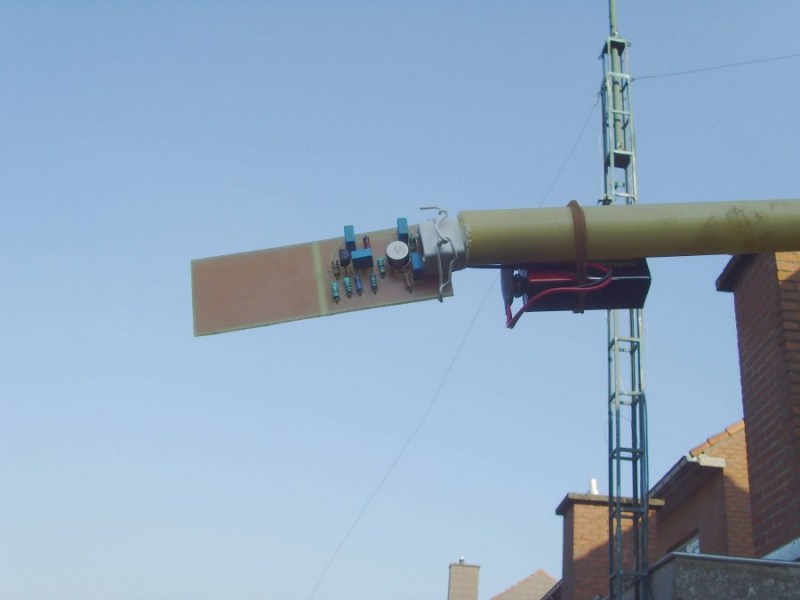
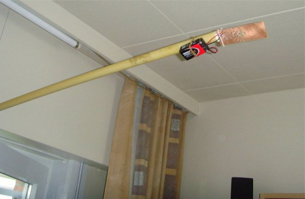
Photos in practice :
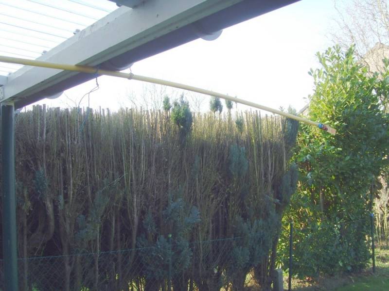
|
|
|
| Outside 4 meters from the house in the open air | Detail of the HF PCB + the 9V battery | No more reception indoors! |
The receiver
The intention was to use this antenna for SDR reception, so that was also tested.
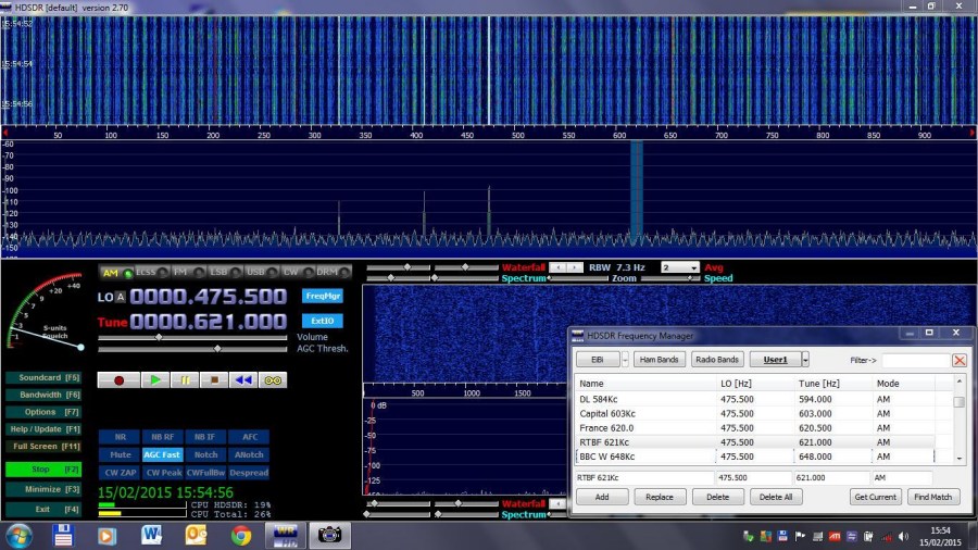
We use a PC or a Laptop, with the HAM program HDSDR (or another), with which we can make a number of observations and pseudo
able to take measurements.
To compare, we do the opposite way:
we try to start with finding the best signal reception with an outdoor setup,
after which we systematically get closer to the house, and see what happens to the signal.
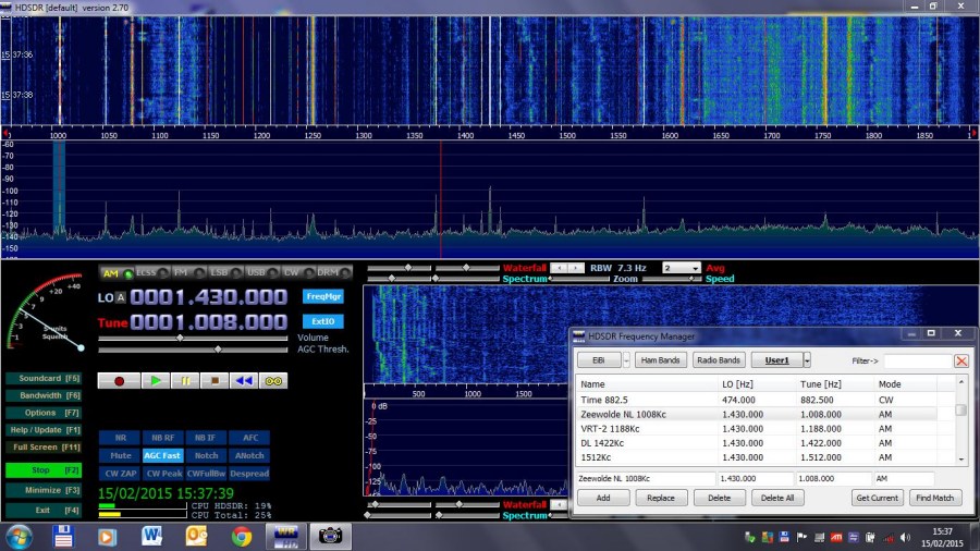
A good test is to look for some NL medium wave stations, which are sometimes difficult to receive during the day. On the screen we see the reception of NL Radio5 at 1.800kHz, which is quite good.
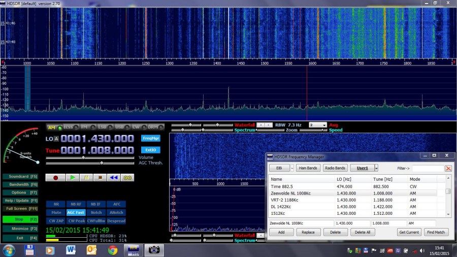
Reception screen, 2 meters from the house, under a plastic shelter: Click on the picture for a larger versionHere we see that the reception at 1,800 kHz is already strongly weakened. French stations, which are very strong, continue to be well received.
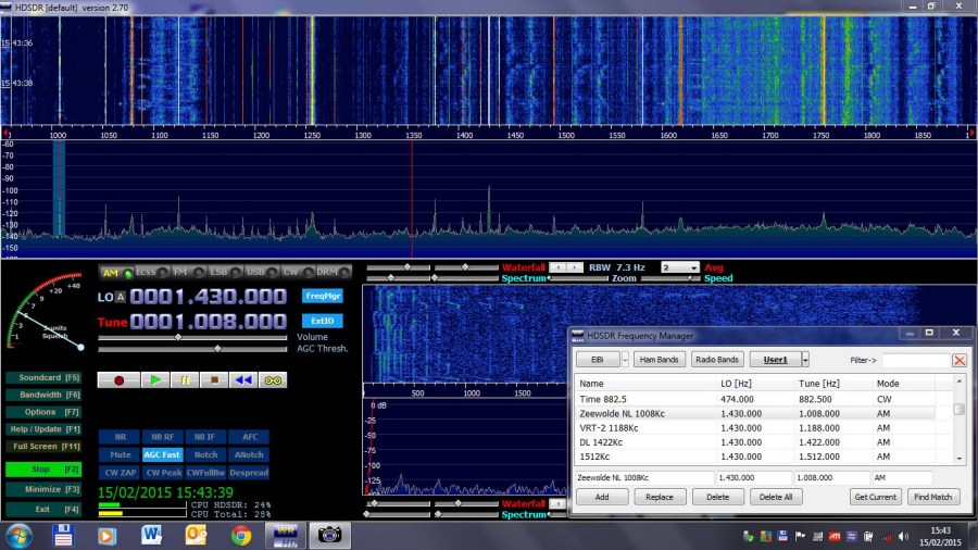
Reception screen, 1 meter from the house, under a plastic shelter: Click on the picture for a larger version
At 1m from the outer wall we see that the NL station has almost completely disappeared. You can already see that the interference is getting stronger, in the form of more and stronger "noise" curtains.
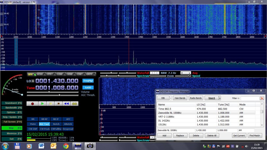
Indoor reception screen at 2 meters from the window: Click on the picture for a larger versionInside the house the reception is very bad. More interference radiation can be seen, and there are no more clear signals. French stations are also practically no longer available.
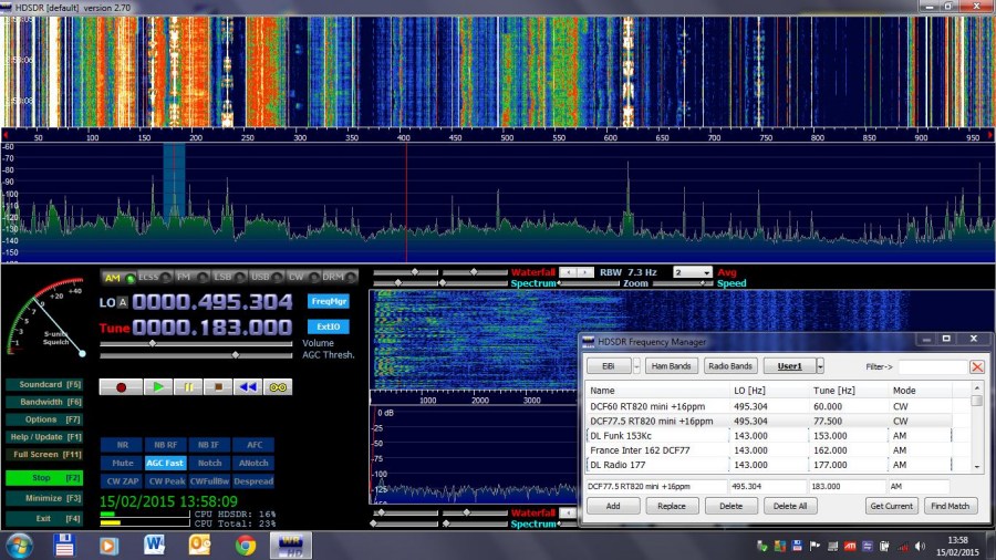
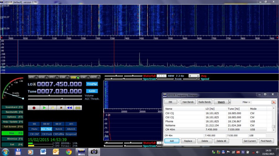
Some frequency bands:
|
|
| Start of the HF spectrum with some strong French stations | Spectrum of the 40m Amateur band (better at night) |
The 40m band could be better, if there are conditions, but a few CW and Phone signals can be seen here already.
|
|
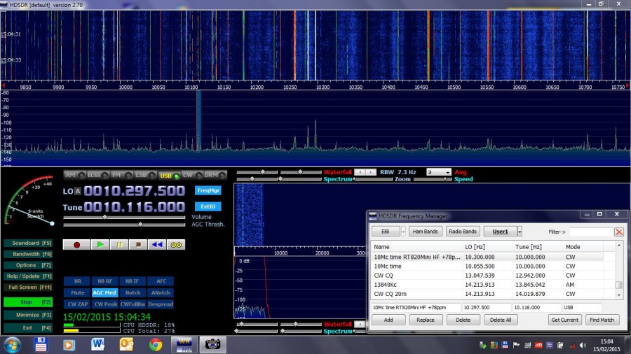
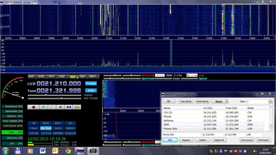
| The 10MHz www time transmitter, and a few CW and Voice signals. | The 10m Amateur band band, with lots of CW signals and Voice stations |
Click on the picture for a larger version
The 10MHz www time transmitter comes through weak (better at night),
and a few CW and Voice stations can be heard as well.
On 21MHz, the 10m band, with many beautiful CW signals and Voice stations.
This shows that the antenna is still working above 21MHz.
Here is the MiniWhip power supply OFF : look what a difference ! Nothing more than false jamming signals and jamming pulses can be seen.
References (Some may no longer work):Also look out for the Slim-line version: ON1BES mini_whip_slim_line_nl
PA0RDT-Mini-Whip.pdf
PA4NIC MiniWhip-pagina
Technical pages :
PA4RDT Mini-Whip_English.pdf
PA3FWM projects miniwhip
PA3FWM technotes Grounding
This antenna is very suitable for my SDR HF UP converter:
SDR HF-Upcovertor v3.0 on1bes at Scarlet.be
