ON1BES Labo 2020 |
SDR HF-Upcovertor v3.0 |
 Back to Home-page |
Voor NL versie klik hier
The smallest SDR Upconvertor you known? Let me know !
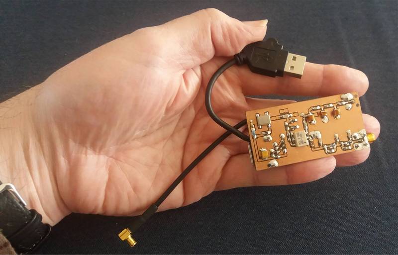 This version 3.0 goes back to basics.
It is a design for the self-builder, who still has some SMD parts in the drawer.
On the PCB there is 1 HF input and 1 VHF output, and a USB input chassis. As a mixer you can use an old IE-500 or SBL-1, or a modern ADE-1 diode ring mixer. For the coils it is better to use air coils instead of Ferrite coils.
The mixer / oscillator operates at 125MHz, so that all types of SDR dongles can be used. The PCB is designed for SMD parts and standard available coils. But it is still possible to use self-made small air coils. The filter values can then be adjusted a bit, by bringing these coils close to the requested coils values. The filter calculations are done with the program RFSim99 (in the Downloads section). As a shield you can saw a few pieces of copper PCB, or cut a few strips from a tin cookie box and solder them around the PCB.
Bandplan:
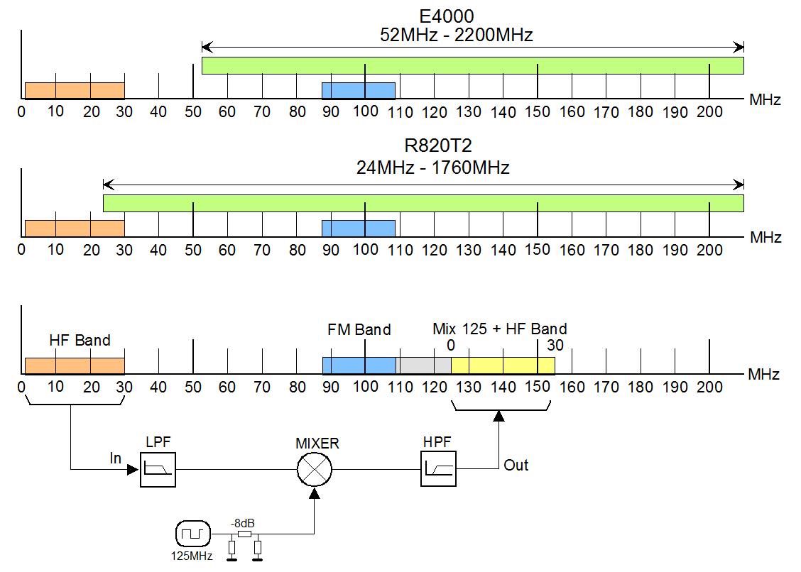
To be able to receive something below 30MHz with our RTL-SDR dongle, we need a convertor that converts 30MHz to a frequency above 50MHz, which we can receive with a normal RTL-SDR dongle. We choose 125MHz as the starting frequency, so as not to conflict with the FM Radio band. Look at the Band Plan below to view the mixer system:* An older E4000 dongle receive from 52MHz to 2200MHz, a newer R820T2 dongle receive from 24MHz to 1760MHz.
Click on figure for bigger view
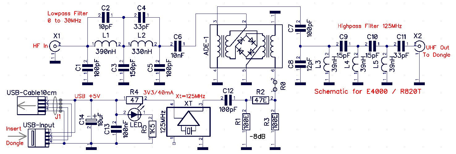
The schematic for a ADE-1 version :
Click on figure for bigger view
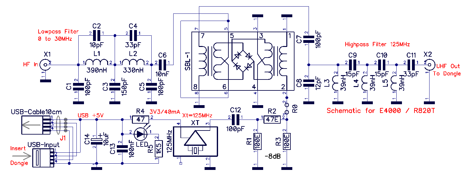
The schematic for a IE-500 or SBL-1 version :
Click on figure for bigger view
Signal flow:
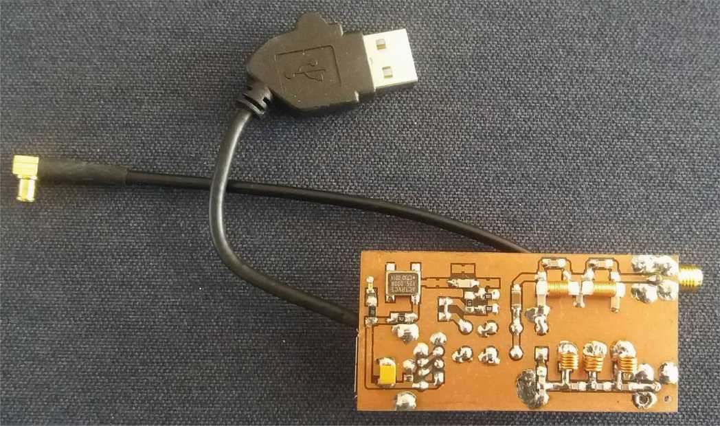
The incoming antenna signal passes through a sharp 0 to 30MHz low-pass filter. Then the signal goes to the input of a diode ring mixer (type ADE1, IE-500 or SBL-1). The output signal from an active 125MHz crystal oscillator goes via an 8dB path, also to the diode ring mixer. There, both are mixed in the ring mixer. This gives the output a sum and difference signal of the antenna signal with the crystal signal of 125MHz. If we add 0-30MHz to the 125MHz signal, then the 30MHz HF band is also on 125MHz to 155Mhz, which we can receive fine with our SDR dongle. The mixer's output signal goes through a high-pass filter, which starts at +/- 124MHz. The purpose of this filter is to suppress strong interference signals from the FM Band. The 5V power supply of the crystal block comes from the PC via a short USB cable, scrapped from an old USB mouse. USB Pin1, in series with a 47 Ohm resistor, supplies 3.4V to the crystal block. There is an LED on this to check the power supply. Pay attention to the numbering and colors of the USB wires, because there are sometimes differences with other cables. The rest of the schedule does not require power. The antenna input connector is an SMA type, but can also be an RCA (audio chassis). A small piece of RG174 type coax (15cm) is soldered to the VHF output of the PCB, and at the other end is an MCX connector, which fits the SDR dongle antenna input (see photo). This cable can be recovered from the supplied rod antenna that came with your SDR stick. I myself used half of a purchased MCX to MCX cable of 30cm (Ebay).Importent note:
1) If we take pin 5 as input on the SBL-1, we can receive almost from 0 MHz to 30 MHz, instead of 100kHz to 30MHz.
2) It is recommended NOT to solder the ground wire to the shield of the USB cable to the PCB.
It has been found that this reduces the environmental interference on the cable shield, therefore the earth of the antenna cable must NOT be connected to the ground of the USB connection.
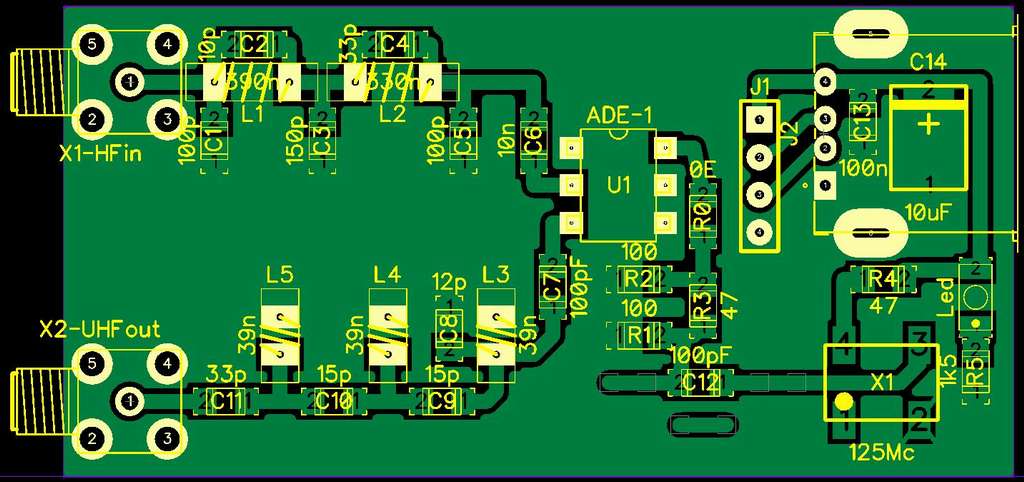
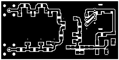
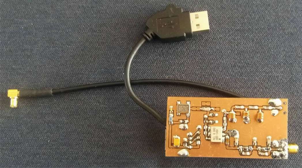
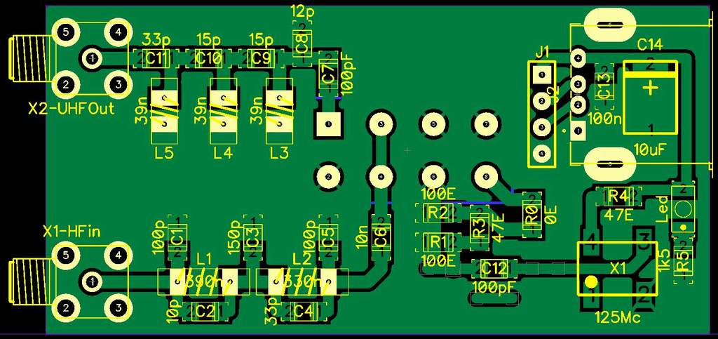
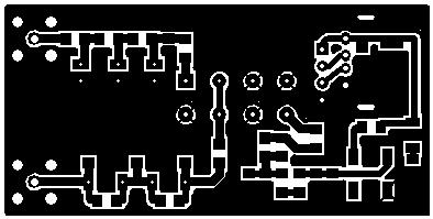
PCB, mask and build:
|
|
|
| Assembly ADE-1 | Mask ADE-1 | Photo |
|
|
|
| Assembly SBL-1 | Board SBL-1 | Photo |
The PCB is double sided. Drill the necessary holes with 1.2 mm for the 2 SMA connectors and 1.0 mm for the USB (and SBL-1). Do not drill holes for the SMD parts and coils! Remove with a 3mm drill bit, on the ground side, the copper around the holes, which should not make a connection to ground.
Attention: the SMA Out connector is NOT placed - the short cable with the MCX connector is soldered to this (see photo).
Making the coils :
 |
 |
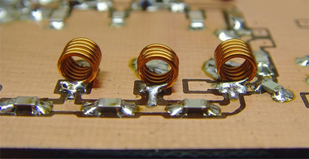 |
| The HF Coils | The VHF Coils | Solder VHF Coils without ends |
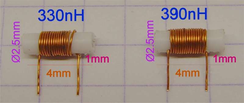
You can make the coils easy for the input and output filters ( coils 330nH and 390nH on a plastick ear-stick = 2,5mm ). The dimentions are:
- the 390nH coil L1 : Ø wire = 0.25mm, ear-stick former = 2.5mm, windings = 16, coil lenght = 4mm.
- the 330nH coil L2 : Ø wire = 0.25mm, ear-stick former = 2.5mm, windings = 14, coil lenght = 4mm.
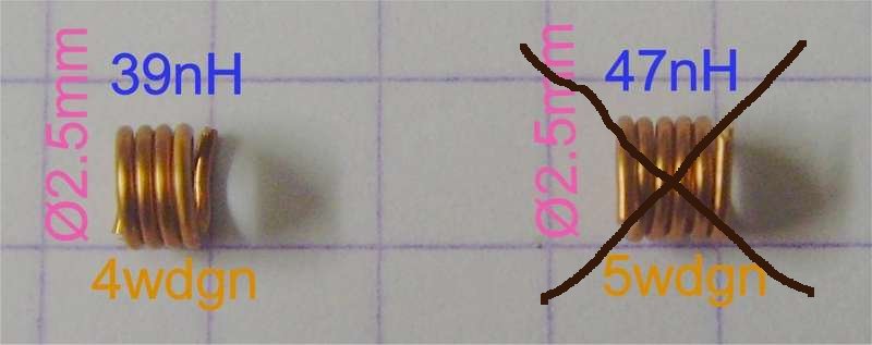
- the 39nH coils L3, L4, L5 : Ø wire = 0.5mm, temporary ear-stick former = 2.5mm, windings = 4, closed together.
- Edit: the 47nH coil L3 and L5: are replaced with 39nH. See values in the schematic. 47nH is not used.
Attention: The VHF coils L3-L4-L5 are pure air coils (after wrapping, remove the ear stick). A VHF air coil with a plastic tube is not stable at that high frequency.
Also, the solder ends may only be max. 1.0 to 1.5 mm, no more. see the picture.
Characteristics of the filters:
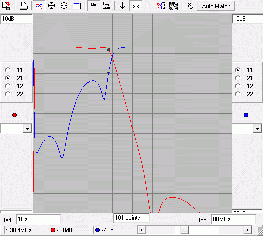
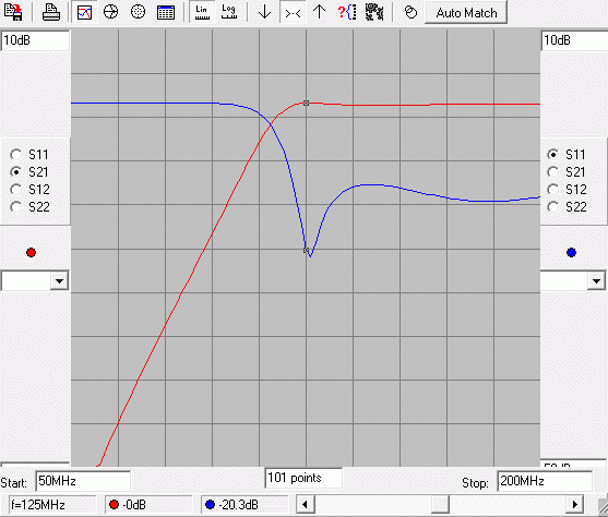
The filters are calculated with RFSim99, an old Windows7/8/XP program but with great prestations. You must first have a installed version on Win XP (32 Bit), and then simply copy the files on a Win10, or the original install does not work (installed files are in the download secion).Here, you see the filter responce diagram(s) in RFSim99:
 |
 |
|
The LP 30 MHz filter |
The HP 125 MHz filter |
Results :
HDSDR is used as SDR software. This has the ability to display the mixed frequency with the 125MHz crystal at the correct reception frequency on the screen. Immediately after construction, during testing, it was clear that there was life in the circuit. My first test antenna was an indoor Magnetic-Loop with C-tuning, enough for some simple reception.Later versions of Up convertors have been tested with an outdoor Mini-Whip antenna with good results.
Below you can see the 2 hardest to receive bands on the HF:
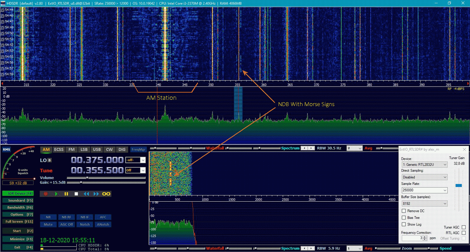
The NDB band from 300kHz to 410kHz, and the 80m HAM band from 3,5 MHz to 4,0 MHz.HSDR and the NDB Baken Band 300kHz-410kHz:
Click a photo for bigger view
The station has Morse code characters on both flanks for station recognition, which you can hear when tuning in.
See the big difference in bandwidth of an AM station compared to an NDB beacon station
HSDR and the 80m HAM Band:
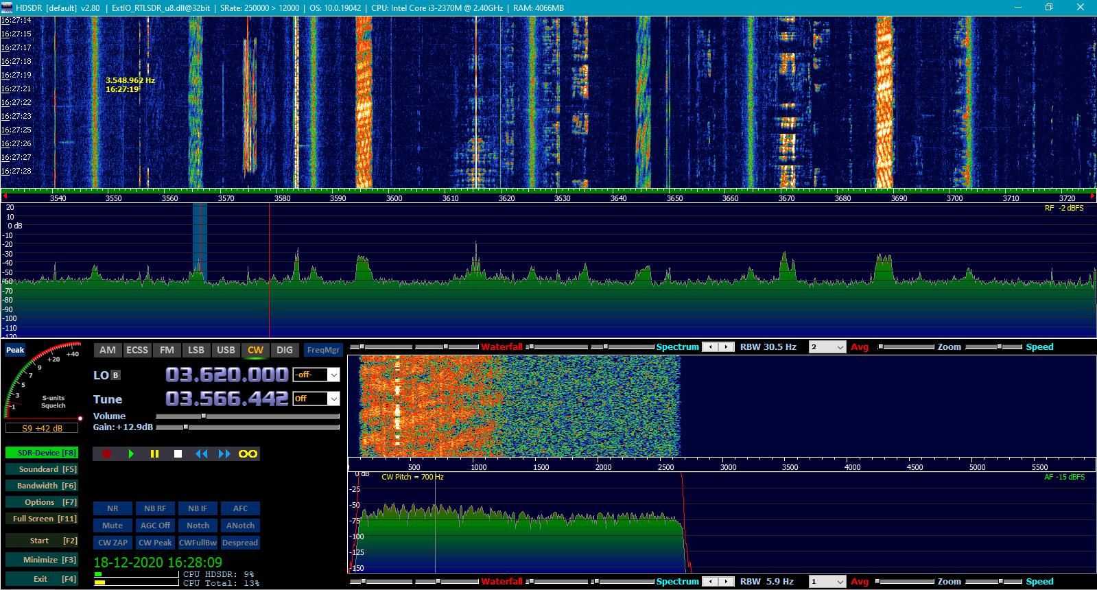
Click a photo for bigger view
The 80m HAM Band also has very narrow signals.
For more reception results and some screens, refer to my other page: HF Upconvertor V1.0
Downloads :
RFSim99: RFSim99.zip
The PCB and circuit files: Upconvertors.zip
I had made a new and tested universal PCB of this version (v5.0).
PCB and circuit in Upconvertors.zip. If interested, contact me.
 mail: on1bes(at)Scarlet.be